You can set different threshold values and record-time settings for the fast-scan recorder and the slow-scan
recorder. The duration of the fault recording depends on the configured record times (pre-trigger time, post-
trigger time, maximum record time). The duration can be extended by repeatedly exceeding or dropping
below the threshold value within the record time (retriggering).
The fault record is ended after reaching the maximum record time in any case.
Level Trigger
Triggering occurs as soon as the measurands exceed (Max. trigger) or drop below (Min. trigger) the
corresponding limiting value. The max level trigger is available for all measurands. The min level trigger
cannot be selected for negative-sequence and zero-sequence systems.
Hysteresis
If a measurand reaches precisely the magnitude of the maximum or minimum limiting value for level triggers
without hysteresis with slight fluctuations, there are repeated, undesirable fault recordings or undesirable
extended recordings due to retriggering. For this reason, hysteresis is permanently set for all level trigger vari-
ables. This hysteresis is 0.2 % for frequency triggers and usually 2 % of the configured threshold value for all
other trigger variables in each channel. The hysteresis is permanently set for very small threshold values.
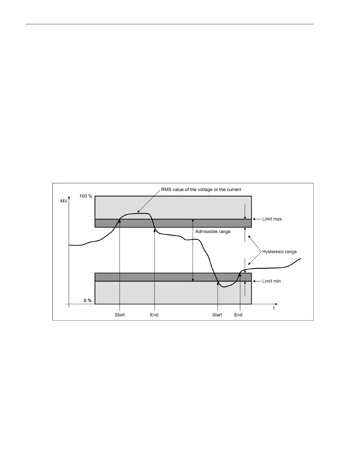
After the limiting value is exceeded or dropped below, the signal must have left the hysteresis range. Only
afterwards can triggering again take place with a repeated exceeding or dropping below a limiting value.
[dwhyst01-130213-01.tif, 1, en_US]
Figure 7-44 Hysteresis
•
Start: At this time, a threshold-value violation is detected.
•
End: At this time, a detected threshold-value violation is canceled.
Gradient Trigger (dM/dt)
The gradient of a signal is the level change over time. The gradient-trigger condition complies with alternating
variables when the difference of 2 measured values is greater than the configured threshold in the interval of
the configured filter time. Differentiation is made between an increasing gradient (dM/dt rise) and a
decreasing gradient (dM/dt drop).
The gradient trigger cannot be selected for negative-sequence or zero-sequence systems.
The figure below shows a typical profile of the power frequency.
7.3.2.3
7.3.2.4
Fault Recorder
7.3 Function Description Analog and Binary Triggers
264 SIPROTEC 5, Fault Recorder, Manual
C53000-G5040-C018-5, Edition 11.2017

 Loading...


