Function Description Analog and Binary Triggers
Overview of Functions
The fast-scan and slow-scan recorders have analog and binary triggers.
Each analog trigger can be configured as primary, secondary or percentage value, relative to the rated value,
and switched into the mode ON, OFF or Test.
Fault records generated in test mode are marked with the Test (Test flag) identifier.
Many trigger combinations can be implemented using a CFC chart. To do this, various indications in CFC
blocks are processed into one CFC output signal that can then, for example, be routed to the External Start.
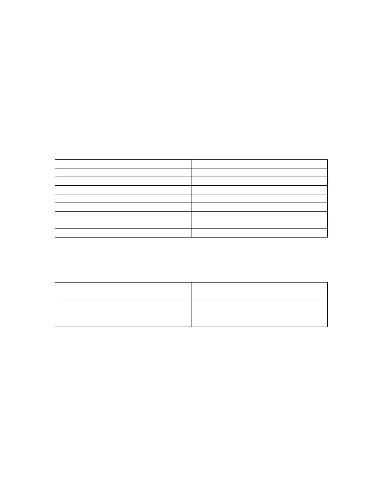
Analog Triggers
Table 7-5 Description of Analog Triggers
Analog Triggers Description
Frequency trigger 1-phase (Also see 7.4.3.1 Overview of Functions)
Frequency trigger 3-phase (Also see 7.5.3.1 Overview of Functions)
Voltage trigger 1-phase (Also see 7.5.1.1 Overview of Functions )
Voltage trigger 3-phase (Also see 7.5.1.1 Overview of Functions )
Current trigger 1-phase (Also see 7.5.2.1 Overview of Functions )
Current trigger 3-phase (Also see 7.5.2.1 Overview of Functions )
Power trigger 1-phase (Also see 7.4.4.1 Overview of Functions)
Power trigger 3-phase (Also see 7.5.4.1 Overview of Functions)
In these function blocks level triggers (Min/Max) and gradient trigger (dM/dt) can be configured.
Binary Triggers
Table 7-6
Using Binary Triggers
Binary Triggers Use
Manual start Function key (via >Manual start)
Binary inputs Via >External start
GOOSE trigger Via >External start
CFC trigger Via >External start
Manual start and External start are each described in the chapters 7.3.3.1 Manual Trigger Start and
7.3.3.2 External Trigger Start .
Manual start and External start are 2 inputs on each recorder that can be used to start recording. The func-
tion is identical for both triggers. Manual Start is primarily used during commissioning and maintenance.
External Start is of universal use.
Function Description Analog Trigger
Structure of the Analog Trigger
There are 4 trigger functions available in the fault recorder:
•
Frequency trigger 1-phase (also see 7.4.3.1 Overview of Functions)
•
Frequency trigger 3-phase (also see 7.5.3.1 Overview of Functions)
•
Voltage trigger 1-phase (also see 7.5.1.1 Overview of Functions )
•
Voltage trigger 3-phase (also see 7.5.1.1 Overview of Functions )
7.3
7.3.1
7.3.2
7.3.2.1
Fault Recorder
7.3 Function Description Analog and Binary Triggers
262 SIPROTEC 5, Fault Recorder, Manual
C53000-G5040-C018-5, Edition 11.2017

 Loading...


