Power trigger
Voltage trigger
Current trigger
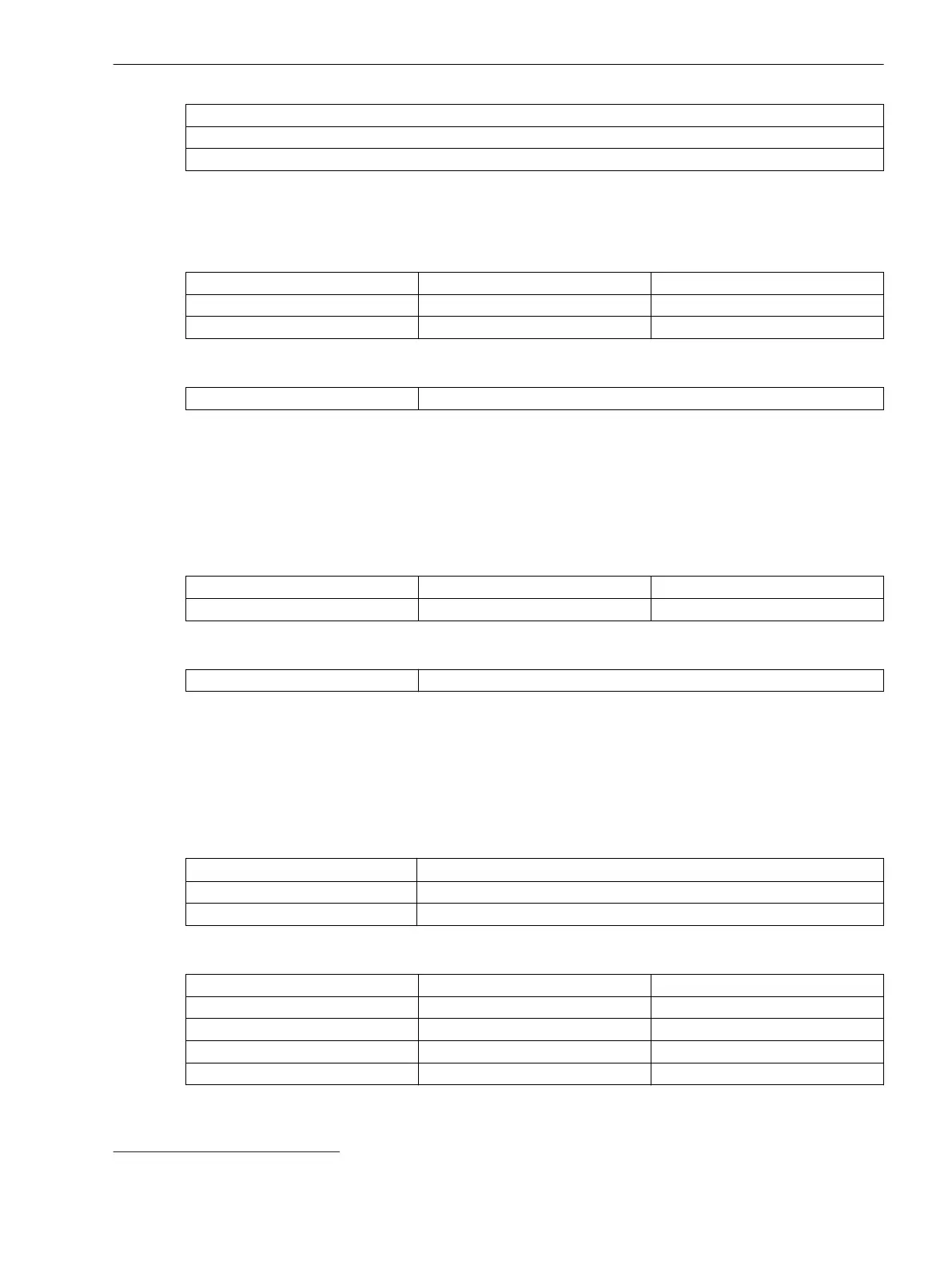
Continuous Recorder
Setting Values
Continuous Recorder Setting Range Increment
Memory capacity 0.200 GB to 14.800 GB Increments of 1
Averaging time 1 s to 900 s
Number of Recorder Instances
Continuous recorder 0 to 5
Signals to be Recorded
Refer to Number of Routable Measured Values (MV) and Binary Tracks (SPS), Page 439
Trend Recorder
Setting Values
Trend Recorder
Setting Range Increment
Memory capacity 0.200 GB to 14.800 GB Increments of 1
Number of Recorder Instances
Trend recorder
0 to 2
Signals to be Recorded
Refer to Number of Routable Measured Values (MV) and Binary Tracks (SPS), Page 439
Measured Values and Binary Inputs
Binary Inputs
Sampling
4 kHz
26
Resolution 1 ms
Refresh rate Event-driven
Number of Routable Measured Values (MV) and Binary Tracks (SPS)
Recorder
Measured Values (MV) Binary Tracks (SPS)
Fast-scan recorder 75 200
Slow-scan recorder 75 100
Continuous recorder 75 –
Trend recorder 100 200
11.4.3
11.4.4
11.4.5
26
Toggle rates applied permanently and greater than 10 Hz are not recommended.
Technical Data
11.4 Recorder Functions
SIPROTEC 5, Fault Recorder, Manual 439
C53000-G5040-C018-5, Edition 11.2017

 Loading...


