[lokenvss-100611-01.tif, 1, en_US]
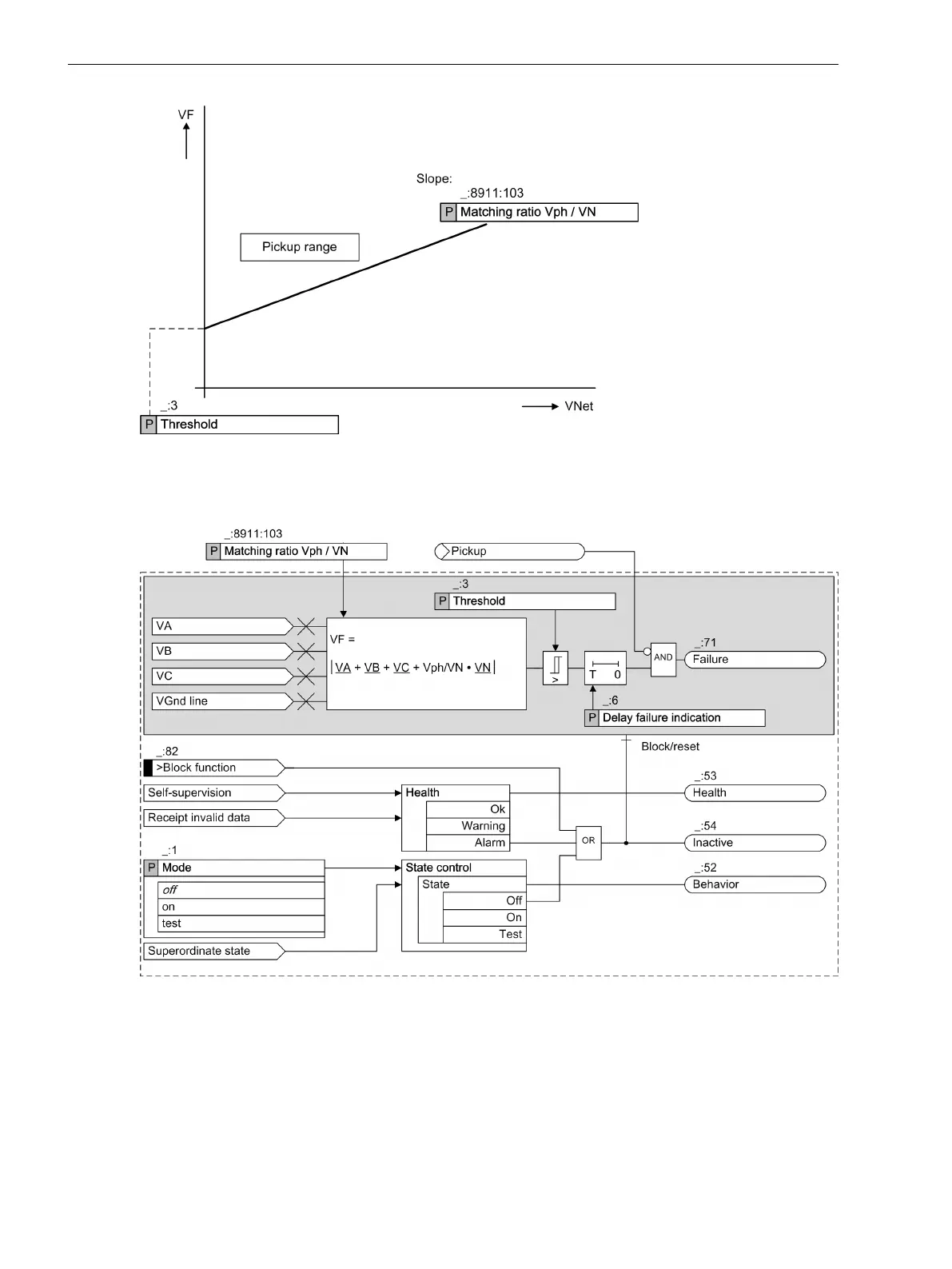
Figure 8-9 Characteristic of the Voltage-Sum Supervision
Logic
[lovssumm-140611-01.tif, 3, en_US]
Figure 8-10
Logic Diagram of the Voltage-Sum Supervision
The device measures the phase-to-ground voltage and the ground voltage of the lines to be protected. The
sum of the 4 voltages must be 0.
Threshold
If the calculated fault voltage (V
F
) exceeds the Threshold, the parameter Delay failure indication
triggers the indication Failure.
Supervision Functions
8.3 Supervision of the Secondary System
376 SIPROTEC 5, Fault Recorder, Manual
C53000-G5040-C018-5, Edition 11.2017

 Loading...


