EasyManua.ls Logo

Siemens SIPROTEC 5 User Manual

Siemens SIPROTEC 5
490 pages
To Next Page IconTo Next Page
To Previous Page IconTo Previous Page
Page #43 background image
[sc7kevor-220213-01.tif, 1, en_US]
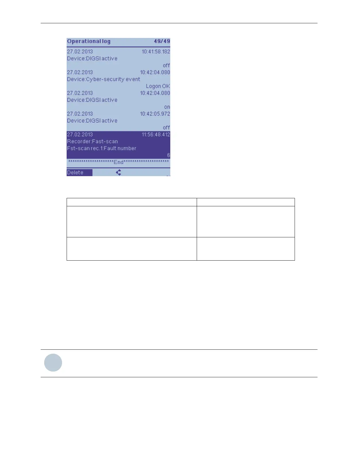
Figure 3-1 On-site Display of an Indication List (Example: Operational Indications)
Menu Path Log
Main menu → Indications → Operational indications
Settings change
User indications 1
User indications 2
Main Menu → Test & Diagnosis → Indications → Security indications
Device diagnosis
Communication indications
²
To reach the desired log from the main menu, use the navigation keys of the on-site operation panel.
²
Navigate inside the log using the navigation keys (top/bottom). You will find the most current indication
at the top of the list. The selected indication is shown with a dark background.
²
Which indications can be shown in the selected log depends on the assignments in the DIGSI 5 informa-
tion routing matrix or is pre-defined.
You will find information about this in the chapter 3.1.5.1 General .
²
Every indication contains date, time and its state as additional information.
²
In some logs you are given the option of deleting the entire indication list by softkey in the footer of the
display.
To know more about this, read chapter 3.1.10 Saving and Deleting the Log .
i
i
NOTE
No password entry is necessary to read indications from the device.
System Functions
3.1 Indications
SIPROTEC 5, Fault Recorder, Manual 43
C53000-G5040-C018-5, Edition 11.2017

Table of Contents

Other manuals for Siemens SIPROTEC 5

Questions and Answers:

Siemens SIPROTEC 5 Specifications

General IconGeneral
SeriesSIPROTEC 5
Communication ProtocolsIEC 61850, DNP3, Modbus
CybersecurityRole-based access control, secure communication
Modular DesignYes
Hardware RedundancyOptional
Operating Temperature-25°C to +70°C
Digital InputsConfigurable, number depends on I/O modules
Digital OutputsConfigurable, number depends on I/O modules
Analog InputsConfigurable, number depends on I/O modules
Current Transformer InputsConfigurable, number depends on I/O modules
Voltage Transformer InputsConfigurable, number depends on I/O modules
Time SynchronizationIRIG-B, SNTP, PTP
Protection FunctionsOvercurrent, Differential, Distance, Over/Under Voltage, Frequency
Housing19-inch Rack Mount
DimensionsDepends on module configuration
WeightDepends on module configuration
Voltage Input24V DC, 48V DC, 110V DC, 125V DC, 220V DC, 250V DC

Summary

Preface

1 Introduction

1.3 Properties of the Fault Recorder

Highlights the specific features and capabilities of the 7KE85 fault recorder.

1.4 Parameterization and Analysis Software

Covers DIGSI 5 for configuration and SICAM PQS/PQ Analyzer for data analysis.

1.5 Scope of Functions

Discusses registration systems in power plants, transmission, and HVDC systems.

2 Basic Structure of the Function

2.2 Adjustment of Application Templates/Functional Scope

Details customization of device functionality using application templates and function points.

2.3 Function Control

Describes how to control the operating modes (On, Off, Test) of functions and function blocks.

3 System Functions

3.2 Measured-Value Acquisition

Details the process and principles of acquiring measured values from analog inputs.

3.4 Date and Time Synchronization

Explains the importance and methods of time synchronization for accurate event logging.

3.7 General Notes for Setting the Threshold Value of Trigger Functions

Provides guidance on setting threshold values for trigger functions.

4 Applications

4.2 Application Template and Functional Scope for the Fault Recorder

Details functional scope and minimum hardware requirements for application templates.

5 Power-System Data

5.4 Application and Setting Notes for Measuring Point Current 3-Phase (I-3ph)

Details application and setting notes for 3-phase current measuring points.

5.5 Application and Setting Notes for Measuring Point Current 1-Phase (I-1ph)

Details application and setting notes for 1-phase current measuring points.

5.6 Application and Setting Notes for Measuring Point Voltage 3-Phase (V-3ph)

Details application and setting notes for 3-phase voltage measuring points.

5.7 Application and Setting Notes for Measuring Point Voltage 1-Phase (V-1ph)

Details application and setting notes for 1-phase voltage measuring points.

6 Function-Group Types

7 Fault Recorder

7.1 Introduction to DIGSI 5

Guides the user through the initial steps of setting up DIGSI 5 for the fault recorder.

7.3 Function Description Analog and Binary Triggers

Explains how analog and binary triggers are used to start fault recordings.

7.4 Trigger Functions 1-Phase

Covers the configuration of single-phase triggers for voltage, current, frequency, and power.

7.5 Trigger Functions 3-Phase

Covers the configuration of 3-phase triggers for voltage, current, frequency, and power.

8 Supervision Functions

8.2 Resource-Consumption Supervision

Monitors application resource consumption, including CFC usage and function points.

8.8 Error Responses and Corrective Measures

Details device errors, their responses, and corrective measures based on defect severity.

10 Functional Tests

11 Technical Data

11.2 Date and Time Synchronization

Details date formats, time sources, and synchronization options for accurate timestamping.

11.4 Recorder Functions

Lists setting values, instances, and signals for Fast-Scan, Slow-Scan, Continuous, and Trend recorders.

A Appendix

A.9 Troubleshooting SDHC Memory Card

Lists common malfunctions of the SDHC memory card, their causes, and remedies.

Related product manuals