ENGINE GENERAL INFORMATION AND DIAGNOSIS (TBI FOR G10) 6-53
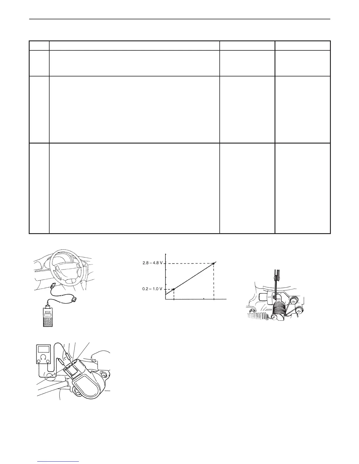
Fig. 1 for Step 2 Fig. 2 for Step 2
Fig. 3 for Step 3
Closed
(condition “A”)
Fully open
Throttle Opening
Condition “A”
Clearance between throttle lever and
throttle stop screw is less than 0.35 mm
(0.014 in.).
clearance
“1”
“3”“4”
INSPECTION
STEP ACTION YES NO
1 Was “ENGINE DIAG. FLOW TABLE” performed? Go to Step 2. Go to “ENGINE
DIAG. FLOW
TABLE”.
2 Check TP Sensor and Its Circuit.
1) Turn ignition switch OFF and connect SUZUKI scan tool to
DLC.
2) Turn ignition switch ON and check TP sensor output
voltage when throttle valve is at idle position and fully
opened. See Fig. 1 and 2.
Dose voltage vary within specified value linearly as shown in
figure?
If voltmeter was
used, check
terminal C01-6 for
poor connection.
If OK, substitute a
known-good ECM
(PCM) and
recheck.
Go to Step 3.
3 Check TP Sensor.
1) Turn ignition switch OFF.
2) Disconnect TP sensor connector.
3) Check for proper connection to TP sensor at each terminal.
4) If OK, then measure resistance between terminals and
check if each measured value is as specified below.
See Fig. 3.
Between 1 and 4: 2.87 – 5.33 kΩ
Between 1 and 3: 100 Ω – 20 kΩ, varying according to
throttle valve opening.
Are measured values as specified?
High resistance in
“Lg”, “Lg/W” or
“G” circuit.
If wire and
connection are
OK, substitute a
known-good ECM
(PCM) and
recheck.
Replace TP
sensor.

 Loading...


