6E1-24 ENGINE AND EMISSION CONTROL SYSTEM (TBI FOR G10)
VEHICLE SPEED SENSOR (VSS) For M/T
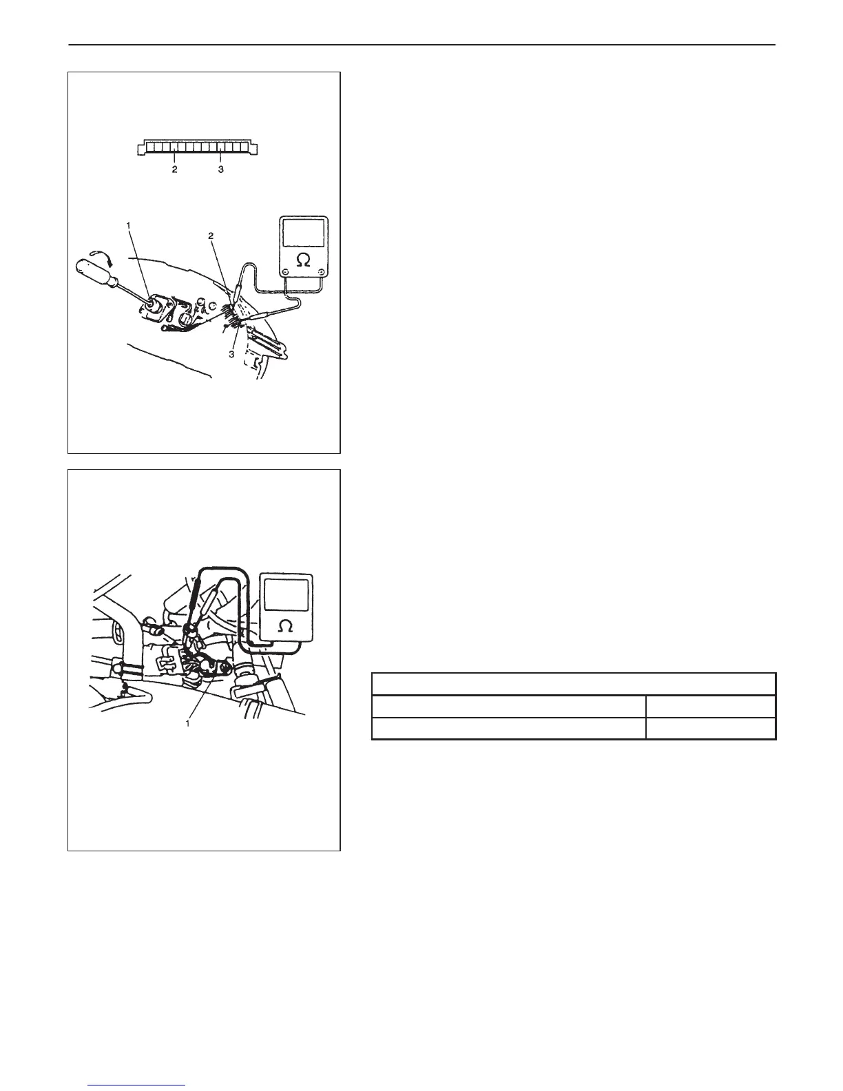
INSPECTION
1) Disconnect negative cable at battery.
2) Remove combination meter from instrument panel.
3) Connect ohmmeter between “VSS” terminal (2) and “GND” ter-
minal (3) of combination meter and turn cable joint (1) of
speedometer with a screwdriver. Ohmmeter indicator should
move back and forth between 0 (zero) and ∞ (infinity) 4 times
while cable joint is turned one full revolution.
Replace speedometer if check result is not satisfactory.
4) Install combination meter to instrument panel.
5) Connect negative cable at battery.
VEHICLE SPEED SENSOR (VSS) For A/T
INSPECTION
Vehicle speed sensor (1) itself can be checked on its resistance by
disconnecting connector.
NOTE:
D Function of vehicle speed sensor can be checked by mea-
suring generated pulse as voltage.
D For its measurement, use an analog type voltmeter while
spinning wheels on lift and with selector lever in D position.
Vehicle speed sensor specifications
Coil resistance 100 – 300 Ω
Output voltage at 40 km/h (25 mile/h) approximately 1 V
FUEL LEVEL SENSOR (GAUGE)
Refer to Section 8.

 Loading...


