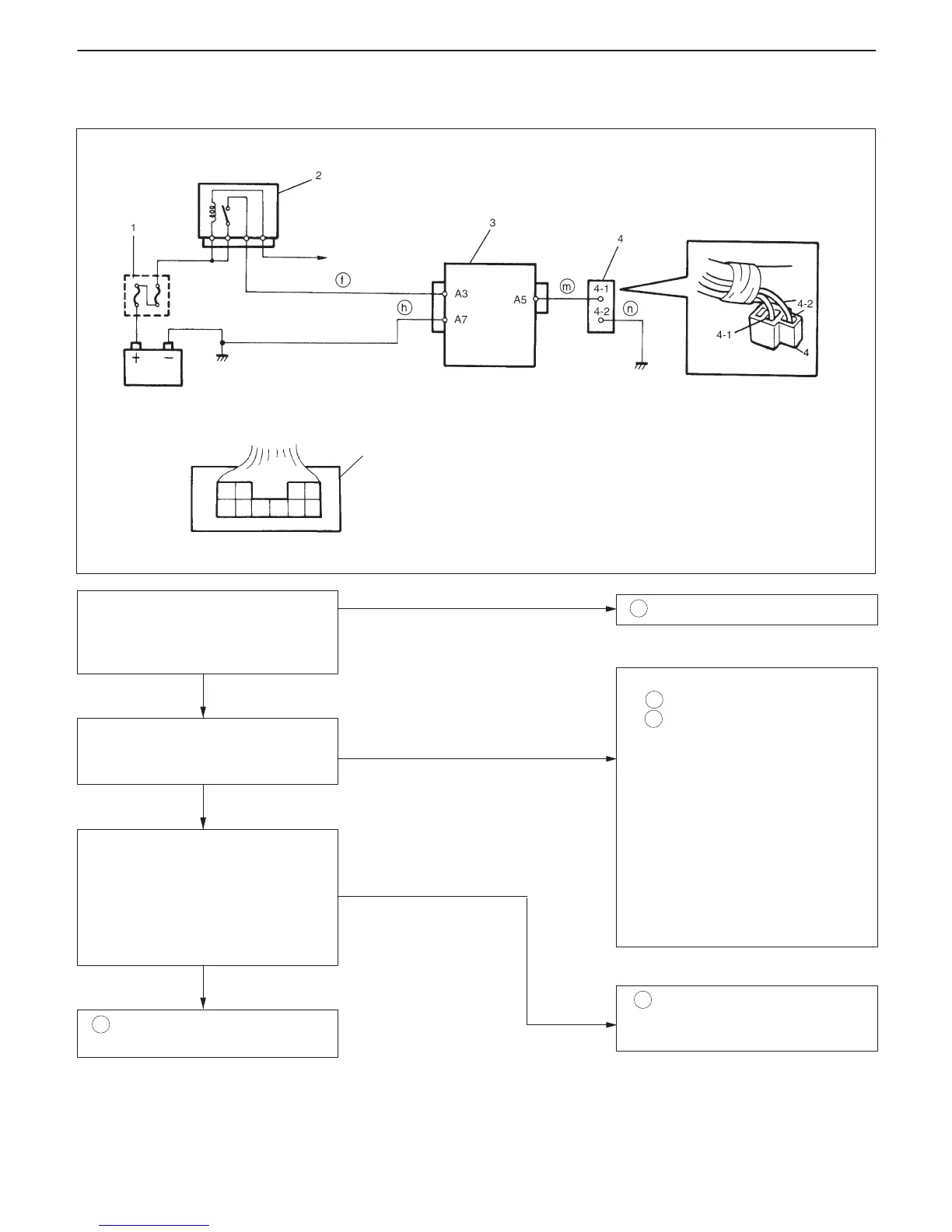
3
To ECM
A5 A7
A3
1. Main fuse
2. Main relay
3. Immobilizer Control Module
4. Immobilizer diagnostic
coupler
4-1. Diagnostic output terminal
4-2. Ground terminal
In cabin
Check voltage between A3 terminal
and body ground with ignition switch
turned ON.
Is it 10 – 14 V?
“ f ” wire open.
1. Connect voltmeter between A5
terminal and body ground.
2. Does voltmeter indicator deflect?
“ n ” wire of ground terminal for im-
mobilizer diagnostic coupler open.
1. Connect voltmeter between diag-
nostic output terminal of immobi-
lizer diagnostic coupler and body
ground.
2. Is it possible to read DTC by
checking deflection of voltmeter
indicator?
D Poor A3, A5 or A7 connection.
D “ h ” wire of A7 terminal open.
D “ m ” wire between A5 terminal and
diagnostic output terminal of im-
mobilizer diagnostic coupler short.
If wire and connections are OK, sub-
stitute a known-good ICM and re-
check.
NOTE:
After replacing with a known-
good ICM, register ECM/ICM code
in ECM and TP code and ECM/ICM
code in ICM by performing proce-
dure described in “Procedure af-
ter ICM Replacement” section.
“ m ” wire between A5 terminal and
diagnostic output terminal of immobi-
lizer diagnostic coupler open.
NO
YES
NO
NO
YES
YES
IMMOBILIZER CONTROL SYSTEM 8G-13
A-1 CODE (DTC) IS NOT OUTPUTTED FROM DIAGNOSTIC OUTPUT TERMINAL OF
IMMOBILIZER DIAGNOSTIC COUPLER

 Loading...


