ENGINE MECHANICAL (G13B, 1-CAM 16-VALVES ENGINE) 6A1-45
INSPECTION
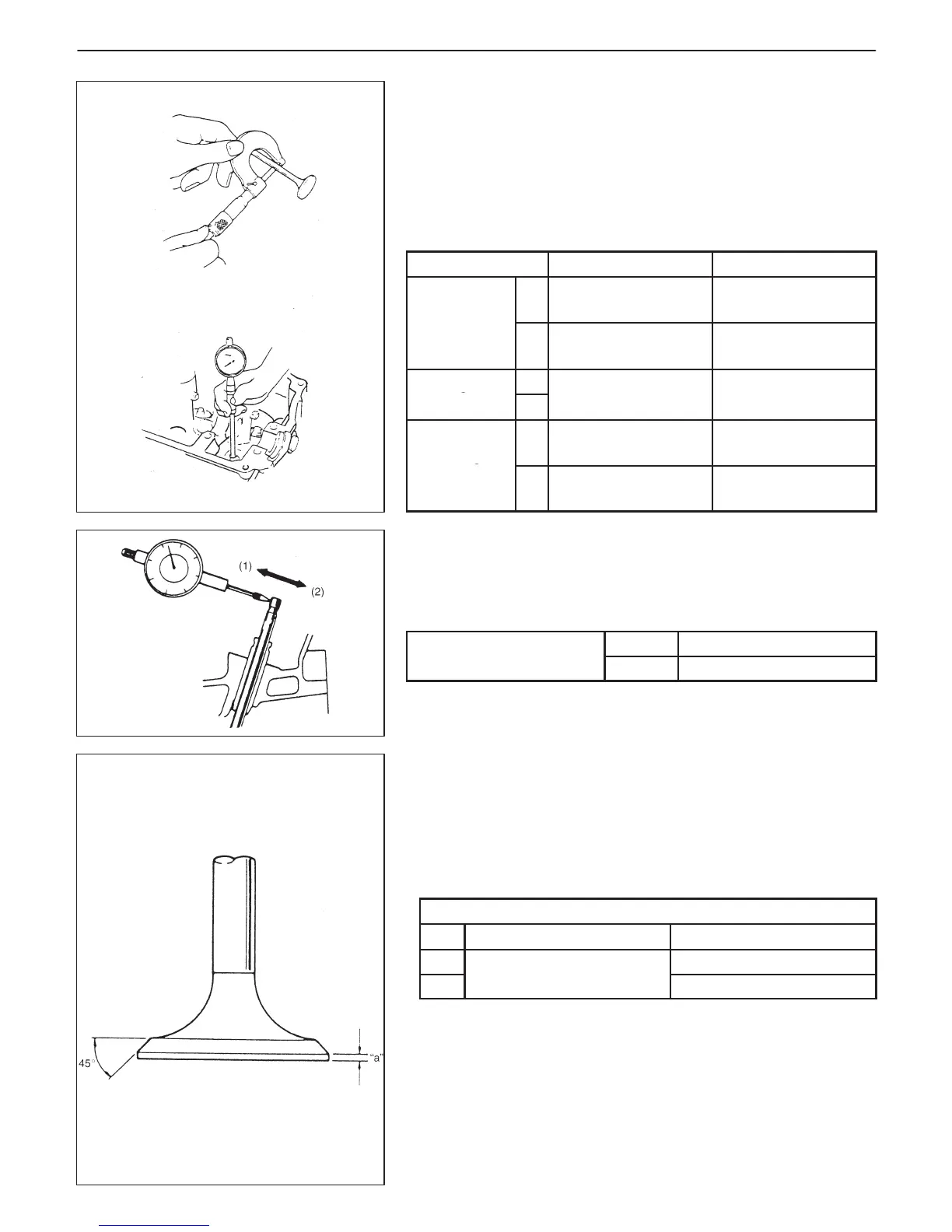
Valve Guides
Using a micrometer and bore gauge, take diameter readings on
valve stems and guides to check stem-to-guide clearance.
Be sure to take reading at more than one place along the length of
each stem and guide.
If clearance exceeds limit, replace valve and valve guide.
Item
Standard Limit
Valve stem
In
5.465 – 5.480 mm
(0.2152 – 0.2157 in.)
–
diameter
Ex
5.440 – 5.455 mm
(0.2142 – 0.2148 in.)
–
Valve guide
In
5.500 – 5.512 mm
clearance
Ex
0.045 – 0.072 mm
(0.0018 – 0.0028 in.)
0.09 mm
(0.0035 in.)
If bore gauge is not available, check end deflection of valve stem
with a dial gauge instead.
Move stem end in directions (1) and (2) to measure end deflection.
If deflection exceeds its limit, replace valve stem and valve guide.
Valve stem end
In 0.14 mm (0.005 in.)
deflection limit
Ex 0.18 mm (0.007 in.)
Valves
D Remove all carbon from valves.
D Inspect each valve for wear, burn or distortion at its face and stem
and, as necessary, replace it.
D Measure thickness “a” of valve head. If measured thickness ex-
ceeds limit, replace valve.
Valve head thickness
Standard Limit
In
0.8 – 1.2 mm
0.6 mm (0.024 in.)
Ex
(0.03 – 0.047 in.)
0.7 mm (0.027 in.)

 Loading...


