IGNITION SYSTEM (SFI FOR G13) 6F1-7
5) Measure secondary coil for resistance.
Secondary coil resistance : 7.6 – 10.2 kΩ at 20_C, 68_F
If resistance is out of specification, replace ignition coil assem-
bly.
6) Install ignition coil assembly.
7) Tighten ignition coil bolts, and then connect ignition coil coupler.
8) Install high-tension cord to ignition coil assembly while gripping
its cap.
CRANKSHAFT POSITION SENSOR
(CKP SENSOR)
Refer to section 6E2 for removal, inspection and installation.
IGNITION TIMING
NOTE:
D Ignition timing is not adjustable. If ignition timing is out of
specification, check system related parts.
D Before starting engine, place transmission gear shift lever in
“Neutral” (shift selector lever to “P” range for A/T model),
and set parking brake.
INSPECTION
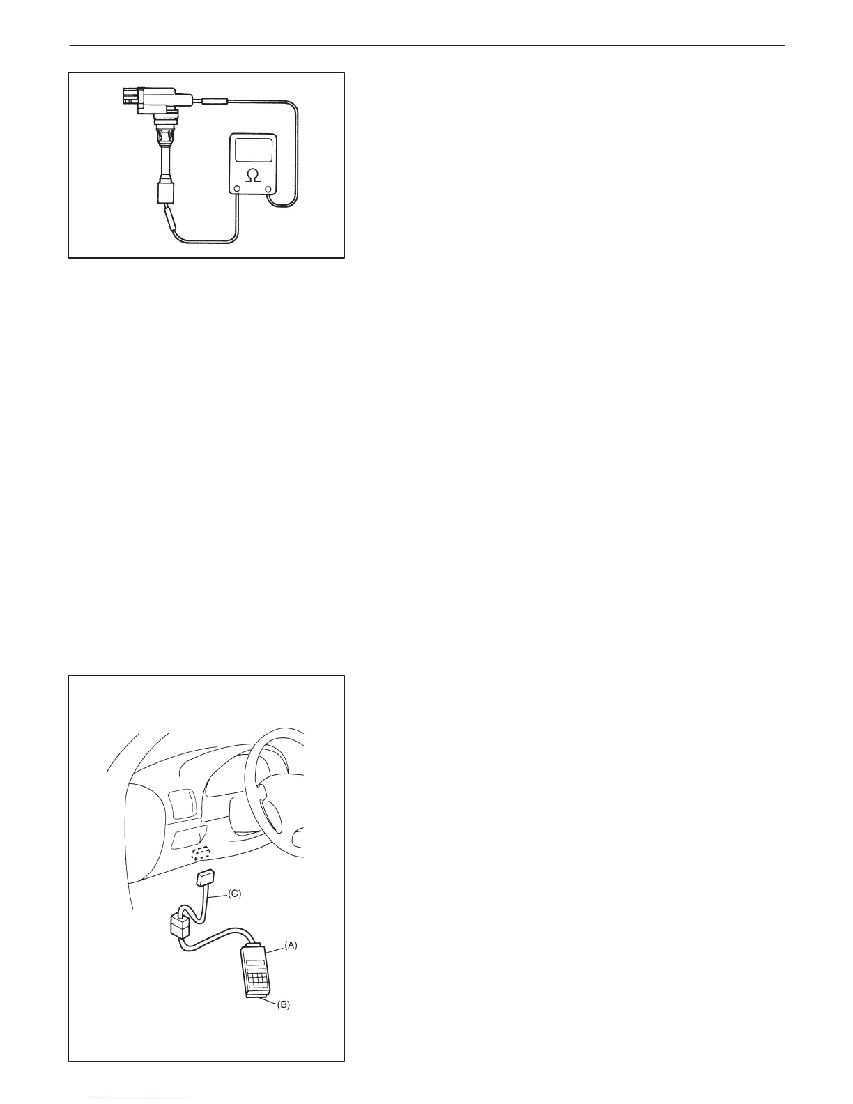
1) Connect SUZUKI scan tool to DLC with ignition switch OFF.
Special Tool
(A): 09931-76011 (SUZUKI scan tool)
(B): Mass storage cartridge
(C): 09931-76030 (16/14 pin DLC cable)
2) Start engine and warm it up to normal operating temperature.
3) Make sure that all of electrical loads except ignition are switched
off.
4) Check to be sure that idle speed is within specification.
(Refer to SECTION 6E2)

 Loading...


