To DLC
“DOME”
Main
fuse
6-94 ENGINE GENERAL INFORMATION AND DIAGNOSIS (TBI FOR G10)
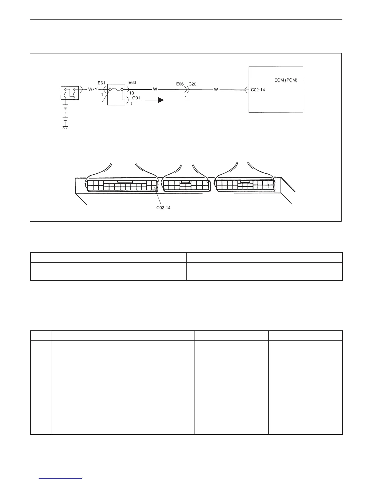
DTC P1510 ECM (PCM) BACK-UP POWER SUPPLY MALFUNCTION
CIRCUIT DESCRIPTION
Battery voltage is supplied so that diagnostic trouble code memory, values for engine control learned by ECM
(PCM), etc. are kept in ECM (PCM) even when the ignition switch is turned OFF.
DTC DETECTING CONDITION
POSSIBLE CAUSE
D Low voltage at terminal C02-14 after starting engine. D “W” circuit open
D ECM (PCM) malfunction
DTC CONFIRMATION PROCEDURE
1) Clear DTC, start engine and run it at idle for 1 min.
2) Select “DTC” mode on scan tool and check DTC.
INSPECTION
STEP ACTION YES NO
1 Check for voltage at terminal C02-14 of ECM
(PCM) connector connected, under each
condition, ignition switch OFF and engine
running.
Is it 10 – 14 V at each condition?
Poor C02-14
connection or
intermittent trouble.
Check for intermittent
referring to “Intermittent
and Poor Connection”
in Section 0A.
If wire and connections
are OK, substitute a
known- good ECM
(PCM) and recheck.
“W” circuit open.

 Loading...


