Main
fuse
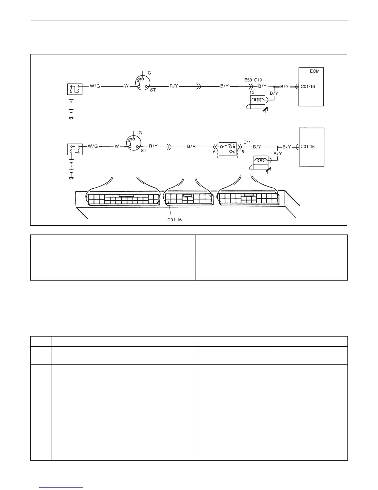
M/ T vehicle
Ignition
switch
(starter
switch)
Starter
A/ T vehicle
Main
fuse
Ignition
switch
(starter
switch)
Transmission
range sensor (switch)
Starter
PCM
ENGINE GENERAL INFORMATION AND DIAGNOSIS (TBI FOR G10) 6-93
DTC P1500 ENGINE STARTER SIGNAL CIRCUIT MALFUNCTION
CIRCUIT DESCRIPTION
DTC DETECTING CONDITION POSSIBLE CAUSE
D High voltage at terminal C01-16 for 3 min. after engine
start.
D Low voltage at terminal C01-16 during starting engine.
: 2 driving cycle detection logic, continuous monitoring.
D “B/Y” circuit open
D ECM (PCM) malfunction
DTC CONFIRMATION PROCEDURE
1) Turn ignition switch OFF.
2) Clear DTC with ignition switch ON, crank engine and run it at idle for 3 min.
3) Check pending DTC in “ON BOARD TEST” or “PENDING DTC” mode and DTC in “DTC” mode.
INSPECTION
STEP ACTION YES NO
1 Was “ENGINE DIAG. FLOW TABLE” performed? Go to Step 2. Go to “ENGINE DIAG.
FLOW TABLE”.
2 Check for voltage at terminal C01-16 of ECM
(PCM) connector connected, under following
condition.
While engine cranking : 6 – 10 V
After starting engine : 0 V
Is voltage as specified?
Poor C01-16
connection or
intermittent trouble.
Check for intermittent
referring to “Intermittent
and Poor Connection”
in Section 0A.
If wire and connections
are OK, substitute a
known-good ECM (PCM)
and recheck.
“B/Y” circuit open.

 Loading...


