ENGINE AND EMISSION CONTROL SYSTEM (TBI FOR G10) 6E1-29
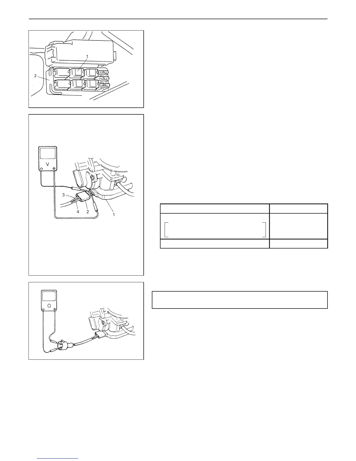
1. ISC actuator relay
2. Relay box
1. EFE heater
2. Rubber cover
3. “Red” wire
4. “Black” wire
ISC ACTUATOR RELAY
INSPECTION
1) Disconnect negative cable at battery.
2) Remove ISC actuator relay from relay box.
3) Structure of ISC actuator relay is the same as that of main relay.
Check its resistance and operation using the same procedure as
that for main relay.
EFE HEATER CONTROL SYSTEM
SYSTEM CIRCUIT INSPECTION
NOTE:
Before inspection, check to make sure that gear shift lever is
in neutral position (with A/T model, selector lever in “P” range)
and that parking brake lever is pulled all the way up.
1) Turn up rubber cover of EFE heater to expose terminal-to-wire
connections.
2) Connect voltmeter to EFE terminals and check for voltage under
each condition given below.
CONDITION
VOLTAGE
Fast idle condition
Coolant temp.: below 80_C (176_F)
Engine speed: over 750 r/min.
Battery
voltage
After warming up (other than above) No voltage
If check results are not as specified in above table, check EFE
heater, relay and wire harness.
3) Cover EFE heater connections with rubber cover.
EFE HEATER
CAUTION:
Do not bend wire harness of EFE heater excessively.
ON-VEHICLE INSPECTION
1) Disconnect EFE heater coupler.
2) Check resistance of EFE heater.
If it is not as specified below, replace.
EFE heater resistance: 0.5 – 3.0 Ω at 20_C (68_F)
3) Connect EFE heater coupler securely.
REMOVAL
1) Remove throttle body according to procedure described pre-
viously.
In this case, however, it is not necessary to disconnect fuel
hoses and engine cooling water hoses from throttle body.
2) Disconnect EFE heater coupler.
3) Remove EFE heater from intake manifold.

 Loading...


