1
2
3
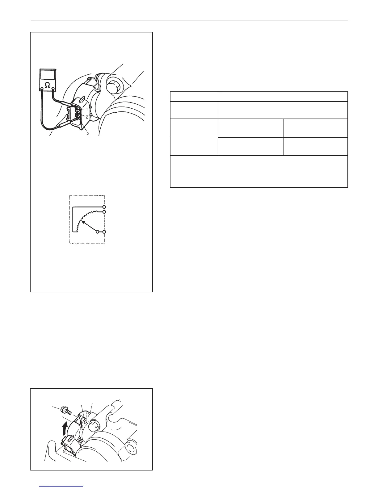
1. Ground terminal
2. Reference voltage terminal
3. Output voltage terminal
(a)
1
2
3
4
6E2-28 ENGINE AND EMISSION CONTROL SYSTEM (SFI FOR G13)
THROTTLE POSITION SENSOR (TP SENSOR)
Inspection
1) Disconnect negative cable at battery and coupler from TP sen-
sor.
2) Using ohmmeter, check resistance between terminals under
each condition given in table below.
TERMINALS
RESISTANCE
Between 1 and
2 terminals
2.5 – 6.0 kΩ
Between 1 and
Throttle valve is
at idle position
0.17 – 11.4 kΩ
3 terminals
Throttle valve is
fully opened
1.72 – 15.50 kΩ
NOTE:
There should be more than 1.5 kΩ resistance difference
between when throttle valve is at idle position and when
it is fully open.
If check result is not satisfactory, replace TP sensor.
3) Connect TP sensor coupler securely.
4) Connect negative cable to battery.
Removal
1) Disconnect battery negative cable at battery.
2) Disconnect coupler from TP sensor.
3) Remove TP sensor from throttle body.
Installation
1) Install TP sensor (1) to throttle body.
Fit TP sensor to throttle body in such way that its holes (3) are
a little away from TP sensor screw holes (2) as shown in left fig-
ure and turn TP sensor clockwise so that those holes align (4).
Tightening Torque
(a): 2.0 N
.
m (0.20 kg-m, 1.5 lb-ft)
2) Connect coupler to TP sensor securely.
3) Connect battery negative cable to battery.

 Loading...


