Output shaft speed sensor (on A / T)
Counter
shaft
gear
ENGINE GENERAL INFORMATION AND DIAGNOSIS (SFI FOR G13) 6-1-89
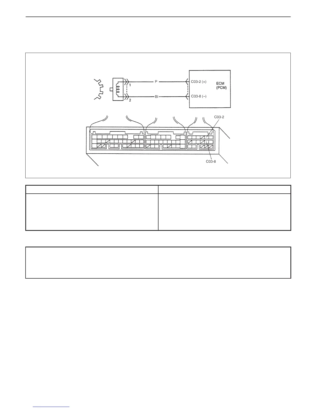
DTC P0500 VEHICLE SPEED SENSOR (VSS) MALFUNCTION FOR A/T
VEHICLE
CIRCUIT DESCRIPTION
DTC DETECTING CONDITION POSSIBLE CAUSE
D While fuel is kept cut at lower than 4000 r/min for
longer than 4 sec.
D VSS signal not inputted.
: 2 driving cycle detection logic, continuous
monitoring.
D “P” or “Bl” circuit open or short.
D Vehicle speed sensor malfunction.
D Foreign material being attached or sensor installed
improperly.
D Gear damaged.
DTC CONFIRMATION PROCEDURE
WARNING:
D When performing a road test, select a place where there is no traffic or possibility of a traffic accident
and be very careful during testing to avoid occurrence of an accident.
D Road test should be carried out with 2 persons, a driver and a tester, on a level road.
1) Turn ignition switch OFF and then ON.
2) Clear DTC and warm up engine to normal operating temperature.
3) Increase vehicle speed to 50 mph, 80 km/h in “2” range.
4) Release accelerator pedal and with engine brake applied, keep vehicle coasting (fuel cut condition) for 4 sec.
or more.
5) Stop vehicle and check DTC and pending DTC.

 Loading...


