ENGINE AND EMISSION CONTROL SYSTEM (TBI FOR G10) 6E1-19
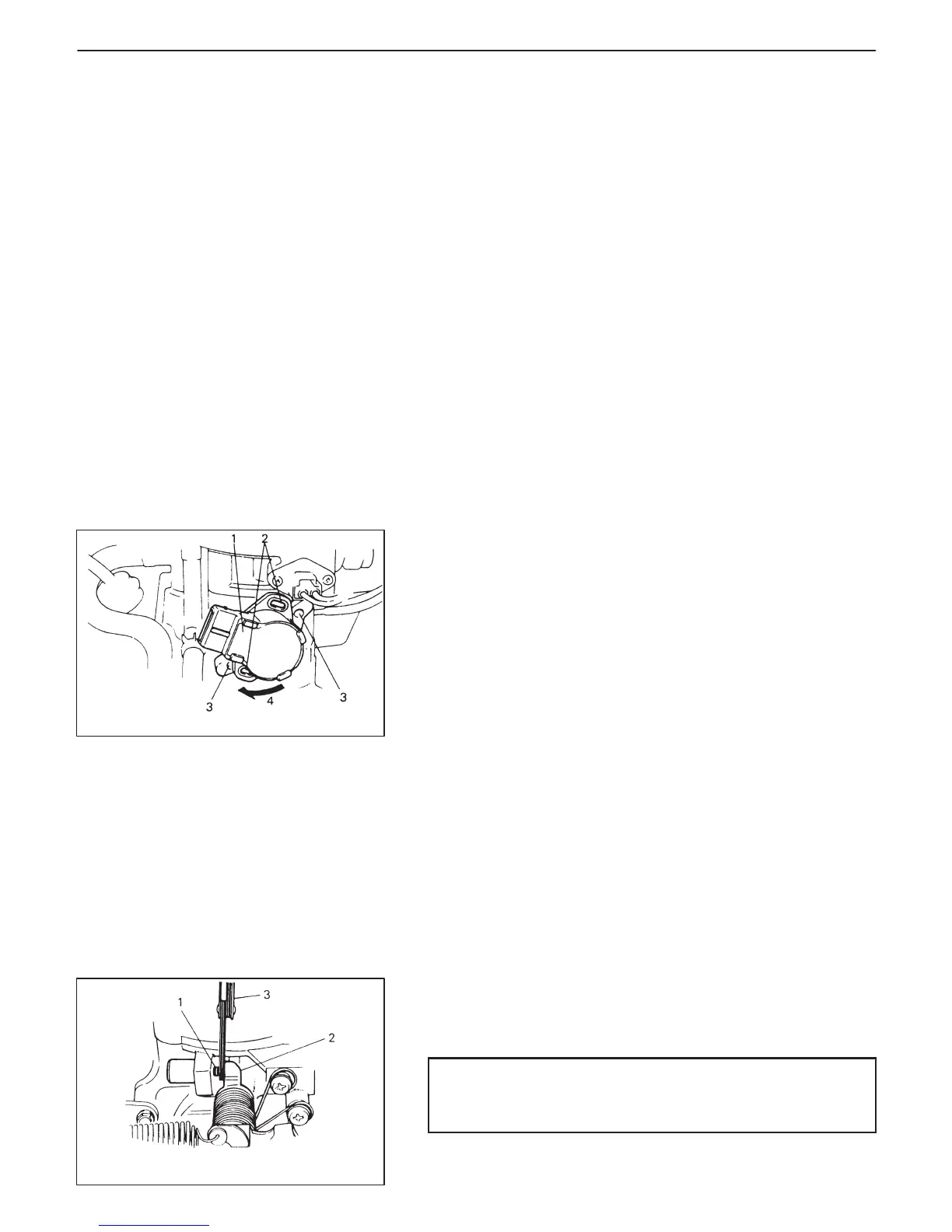
1. TP sensor
2. TP sensor
adjusting holes
3. TP sensor
screw holes
4. Turn TP sensor after
fitting and align holes.
1. Throttle stop screw
2. Throttle lever
3. Thickness gauge
THROTTLE POSITION SENSOR (TP SENSOR)
INSPECTION
Check TP sensor referring to step 2 of DTC P0121 Flow Table. If
malfunction is found, replace.
REMOVAL
1) Disconnect battery negative cable at battery.
2) Remove air cleaner assembly referring to Section 6A.
3) Disconnect coupler from TP sensor.
4) Remove TP sensor from throttle body.
INSTALLATION
1) Install TP sensor to throttle body.
Fit TP sensor to throttle body in such way that its adjusting holes
are a little away from TP sensor screw holes as shown in left fig-
ure and turn TP sensor clockwise so that those holes align.
Then hand-tighten TP sensor screws.
2) Connect coupler to TP sensor securely.
3) Install air cleaner assembly referring to Section 6A.
4) Connect battery negative cable battery.
5) Adjust installation angle of TP sensor according to procedure
described in item “ADJUSTMENT”.
ADJUSTMENT
1) Insert 3.5 mm (0.14 in.) thickness gauge between throttle stop
screw and throttle lever.
CAUTION:
As throttle stop screw is factory adjusted precisely, don’t
remove or adjust it.

 Loading...


