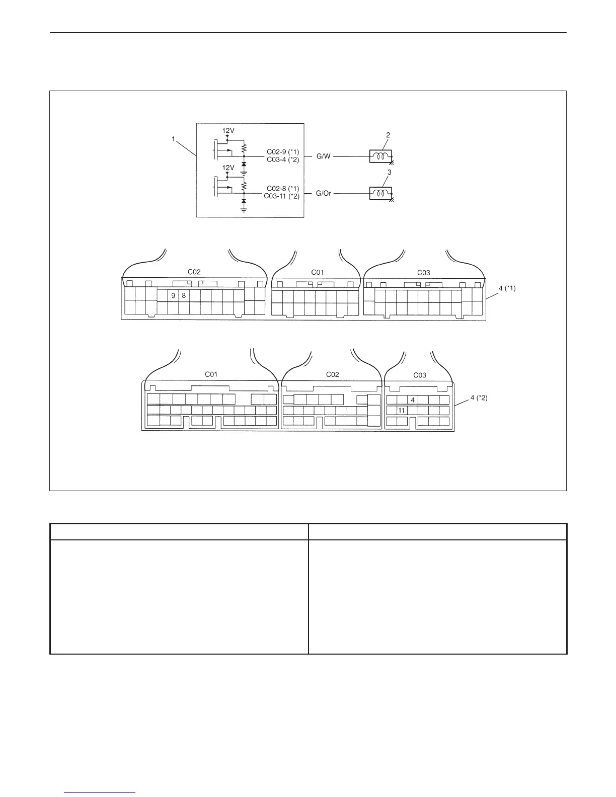
1. PCM
2. Shift solenoid-A (No.1, Direct clutch solenoid)
3. Shift solenoid-B (No.2, 2nd brake solenoid)
4. Terminal arrangement of PCM coupler
(Viewed from harness side)
*1: For G10 engine model
*2: For G13 engine model
7B-26 AUTOMATIC TRANSMISSION (3 A / T) (VEHICLE WITH WU-TWC)
DTC P0753 SHIFT SOLENOID-A (NO.1) ELECTRICAL
DTC P0758 SHIFT SOLENOID-B (NO.2) ELECTRICAL
CIRCUIT DESCRIPTION – Refer to “GENERAL DESCRIPTION” of this section.
DTC DETECTING CONDITION
POSSIBLE CAUSE
Output command from PCM and output voltage do not
agree.
DTC P0753:
D “G/W” circuit open or short
D Shift solenoid-A malfunction
D PCM malfunction
DTC P0758:
D “G/Or” circuit open or short
D Shift solenoid-B malfunction
D PCM malfunction
DTC CONFIRMATION PROCEDURE
1) Turn ignition switch OFF.
2) Clear DTC with ignition switch ON and warm up engine to normal operating temperature at “P” range.
3) Shift selector lever to “D” range for 1 sec. or longer.
4) Shift it to “P” range and check DTC.

 Loading...


