ENGINE AND EMISSION CONTROL SYSTEM (TBI FOR G10) 6E1-25
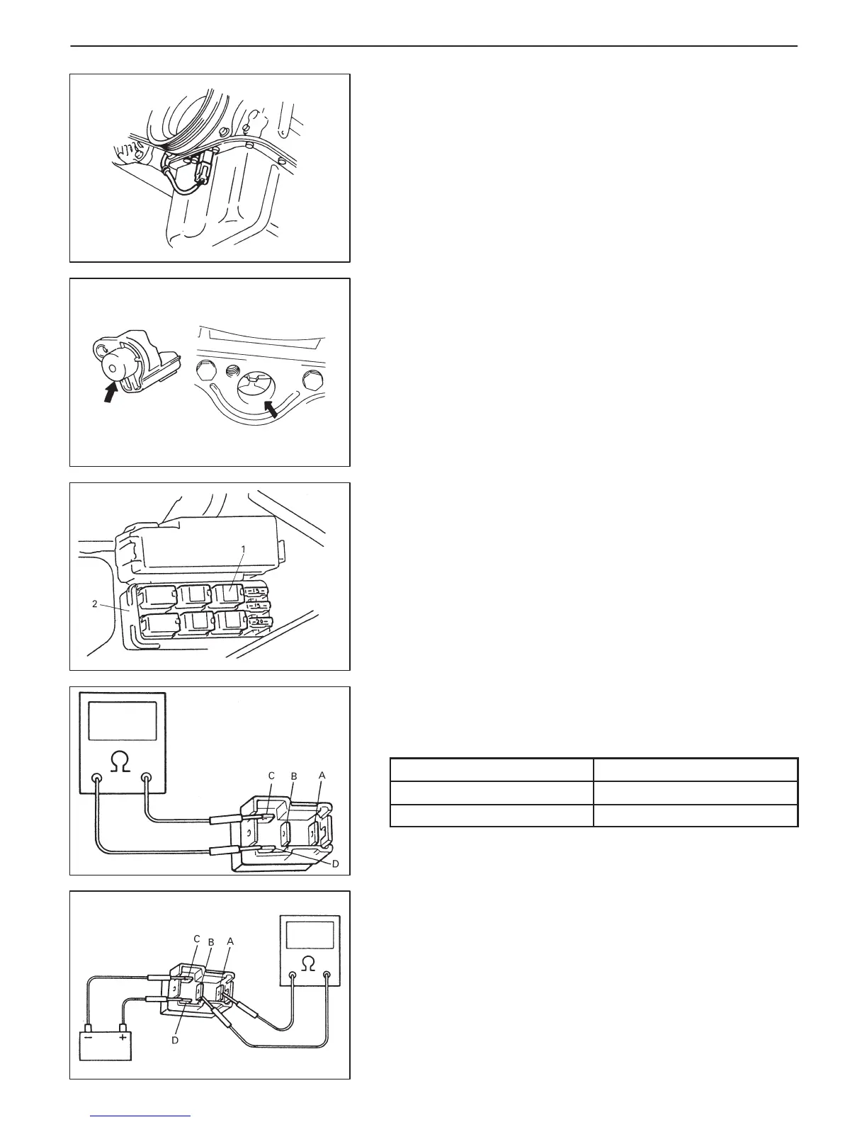
1. Main relay
2. Relay box
CRANKSHAFT POSITION SENSOR
INSPECTION
Check crankshaft position sensor referring to step 1 and 2 of DTC
P0335 Flow Chart. If malfunction is found, replace.
REMOVAL
1) Hoist vehicle.
2) Remove fender apron extension on right side.
3) Disconnect connector from crankshaft position sensor.
4) Remove crankshaft position sensor from oil pan.
INSTALLATION
1) Check to make sure that crankshaft position sensor and pulley
tooth is free from any metal particles and damage.
2) Install crankshaft position sensor to oil pan.
3) Connect connector to it securely.
4) Install fender apron extension.
MAIN RELAY
INSPECTION
1) Disconnect negative cable at battery.
2) Remove main relay from relay box.
3) Check resistance between each two terminals as in table below.
If check results are as specified, proceed to next operation
check. If not, replace.
TERMINALS
RESISTANCE
Between A and B ∞ (infinity)
Between C and D 100 – 120 Ω
4) Check that there is continuity between terminals “A” and “B”
when battery is connected to terminals “C” and “D”.
If found defective, replace.

 Loading...


