8G-8 IMMOBILIZER CONTROL SYSTEM
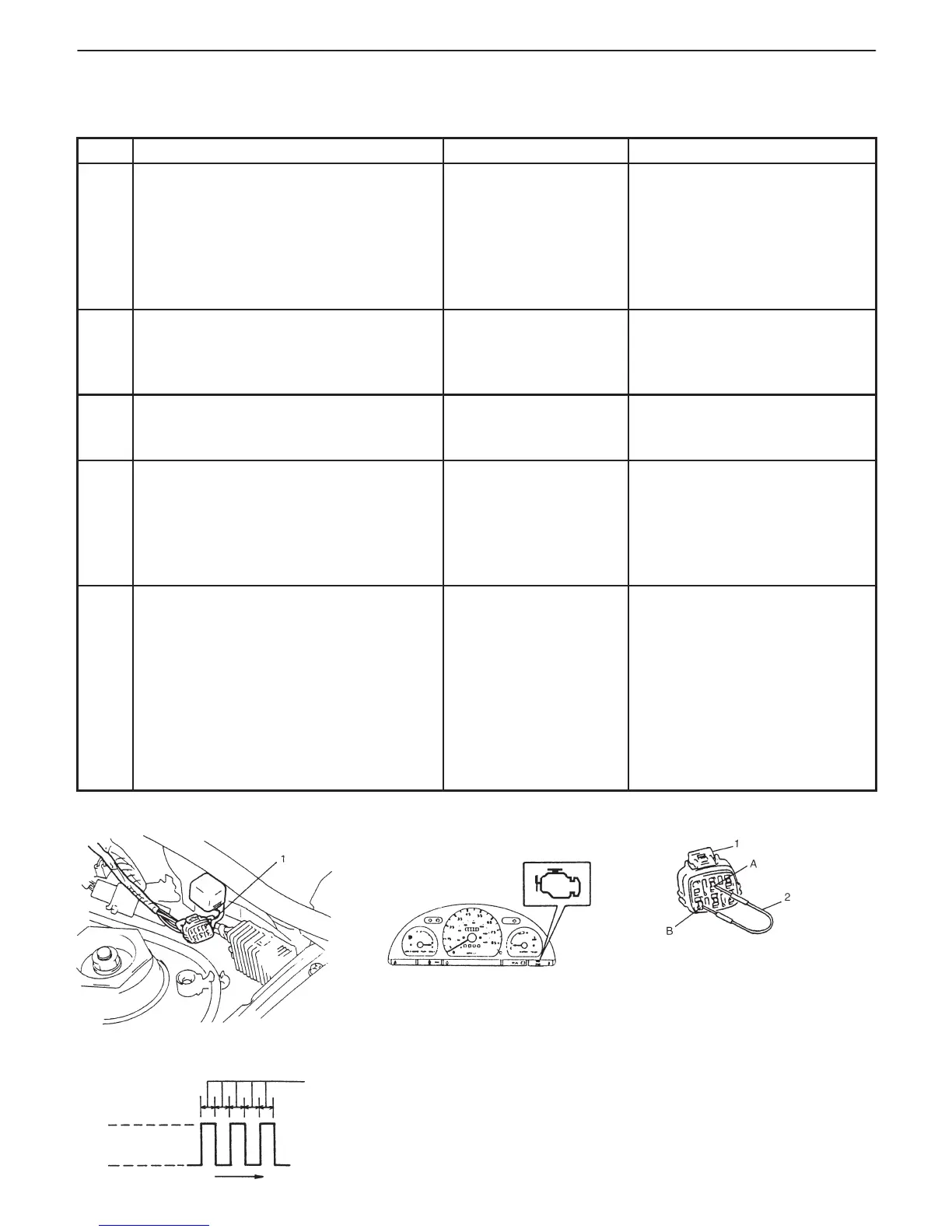
Fig. 1 for Step 1 Fig. 2 for Step 1 Fig. 3 for Step 2
1. Monitor coupler
2. Service wire
A: Diagnosis switch terminal
B: Ground terminal
Fig. 4 for Step 3
“CHECK ENGINE” light
0.5
ON
OFF
TIME (sec.)
DIAGNOSTIC FLOW TABLE
<Vehicle equipped with monitor coupler>
STEP ACTION YES NO
1 1) Make sure that diagnosis switch
terminal in monitor coupler is not
grounded by service wire. See Fig. 1.
2) Check malfunction indicator lamp
while ignition switch is ON (but without
starting engine). See Fig. 2.
Dose malfunction indicator lamp flash?
Go to Step 3. D If malfunction indicator lamp
remains ON, go to Step 2.
D If malfunction indicator lamp
remains OFF, go to
“MALFUNCTION INDICATOR
LAMP CHECK” in Section 6.
2 1) Using service wire, ground diagnosis
switch terminal in monitor coupler.
See Fig. 3.
Dose malfunction indicator lamp flash?
Immobilizer control
system is in good
condition.
Go to “MALFUNCTION
INDICATOR LAMP CHECK” in
Section 6.
3 Dose malfunction indicator lamp flash as
Fig. 4?
Go to Step 4. Go to “MALFUNCTION
INDICATOR LAMP CHECK” in
Section 6.
4 1) Check DTC stored in Immobilizer
Control Module referring to
“DIAGNOSTIC TROUBLE CODE
CHECK (IMMOBILIZER CONTROL
MODULE)” in this section.
Is there any DTC(s)?
Go to flow table for
DTC No.
Go to Step 5.
5 1) Check DTC stored in ECM referring to
“DIAGNOSTIC TROUBLE CODE
CHECK (ECM)” in this section.
Is there any DTC(s)?
Go to flow table for
DTC No.
Substitute a known-good ECM
and recheck.
NOTE:
After replacing with a known-
good ECM, register ECM/
Immobilizer Control Module
code in ECM by performing
procedure described in
“Procedure after ECM
Replacement” section.

 Loading...


