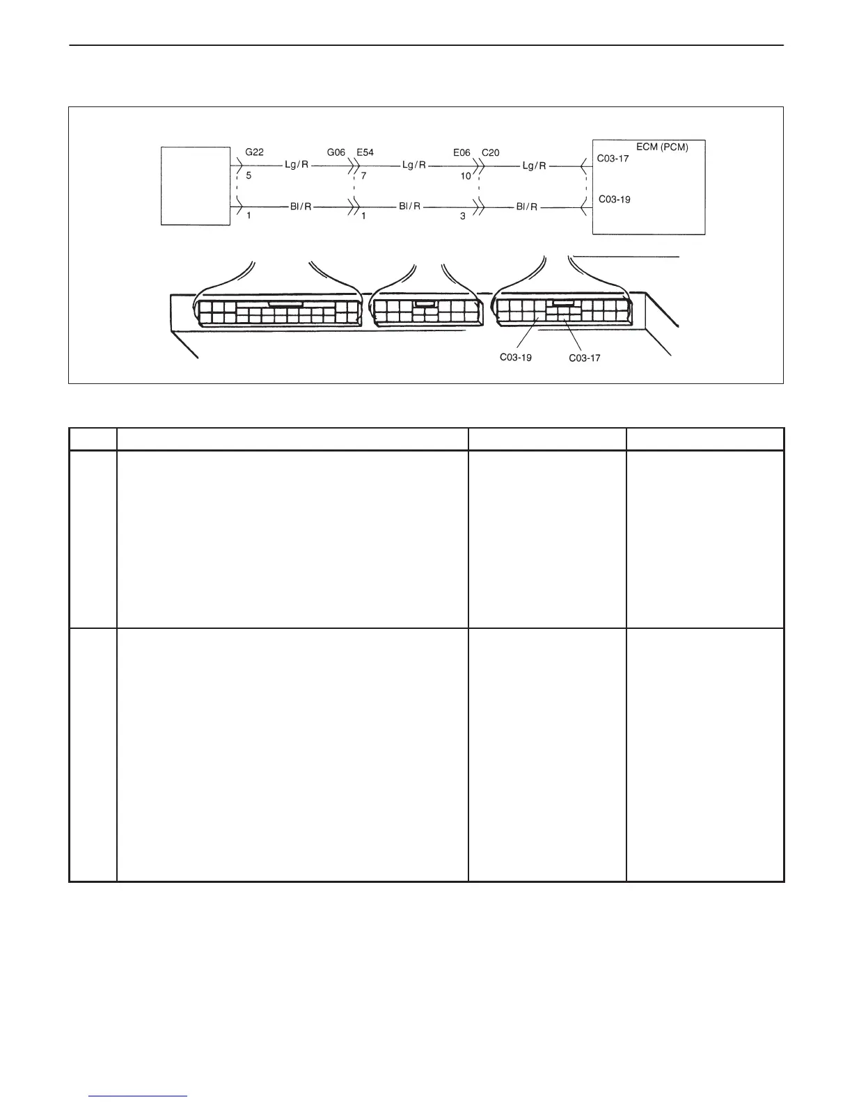
A/C
amplifier
(A / C ON output signal)
(A / C input signal)
6-102 ENGINE GENERAL INFORMATION AND DIAGNOSIS (TBI FOR G10)
TABLE B-4 A/C SIGNAL CIRCUITS CHECK (VEHICLE WITH A/C)
INSPECTION
STEP ACTION YES NO
1 Check A/C (Input) Signal Circuit.
1) Check voltage at terminal C03-19.
While engine running and A/C switch
and/or heater blower switch OFF
(A/C is not operating) : 10 – 14 V
While engine running and both A/C
switch and heater blower switch ON
(A/C is operating) : About 0 V
Are check results as specified?
Go to Step 2. D “Bl/R” wire open or
short.
D Poor C03-19
connection.
D Poor A/C amplifier
coupler connection
or faulty A/C
system.
2 Check A/C ON (Output) Signal Circuit.
1) Check voltage at terminal C03-17.
While engine running and A/C switch
and/or heater blower switch OFF
(A/C is not operating) : About 0 V
While engine running at idle speed
and both A/C switch and heater blower
switch ON (A/C is operating) : 10 – 14 V
Are check results as specified?
A/C control signal
circuits are in good
condition.
D “Lg/R” wire open or
short.
D Poor performance of
ECT sensor, TP
sensor.
D Engine start signal
inputted or
D Poor C03-17
connection.
If none of the above
exists, substitute a
known-good ECM
(PCM) and recheck.

 Loading...


