6E1-30 ENGINE AND EMISSION CONTROL SYSTEM (TBI FOR G10)
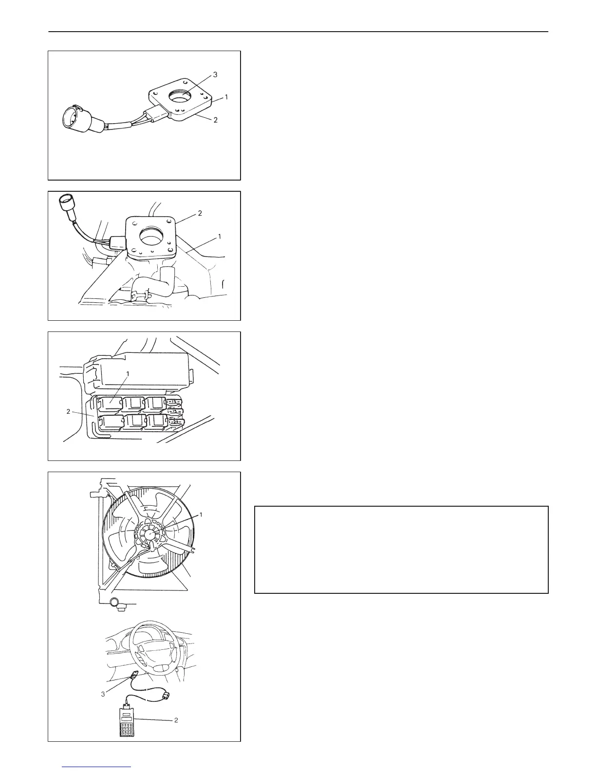
1. Insulator
2. Lower gasket
3. Heater
1. Intake manifold
2. EFE heater
1. EFE heater relay
2. Relay box
1. Radiator fan motor
INSPECTION
D Check lower gasket for damage and deterioration. Replace as
necessary.
D Check heater and insulator for crack, corrosion or any other dam-
age. Replace as necessary.
INSTALLATION
1) Clean mating surfaces of throttle body and intake manifold that
mate with EFE heater.
2) Install EFE heater to intake manifold.
Use new upper gasket.
3) Install throttle body according to procedure described previous-
ly.
4) Connect EFE heater coupler.
EFE HEATER RELAY
INSPECTION
1) Disconnect negative cable at battery.
2) Remove EFE heater relay from relay box.
3) Structure of EFE heater relay is the same as that of main relay.
Check its resistance and operation using the same procedure as
that for main relay.
If found defective, replace.
RADIATOR FAN CONTROL SYSTEM
SYSTEM INSPECTION
WARNING:
Keep hands, tools, and clothing away from engine cooling
fan to help prevent personal injury. This fan is electric and
can come on whether or not the engine is running. The fan
can start automatically in response to the ECT sensor with
the ignition switch in the “ON” position.
Connect SUZUKI scan tool (2) to DLC (3).
Start engine and keep it running to warm it up.
Now check to ensure that radiator fan is started when the coolant
temperature displayed on SUZUKI scan tool reaches 96_C
(205_F).
If check result is not satisfactory, check RFC relay, wire harness,
ECT sensor, ECM, coolant temp. meter and sender gauge unit.
Refer to “DTC P0480 FLOW TABLE” of Section 6 and “COOLANT
TEMP. METER AND GAUGE UNIT” of Section 8.

 Loading...


