AUTOMATIC TRANSMISSION (3 A / T) (VEHICLE WITH WU-TWC) 7B-19
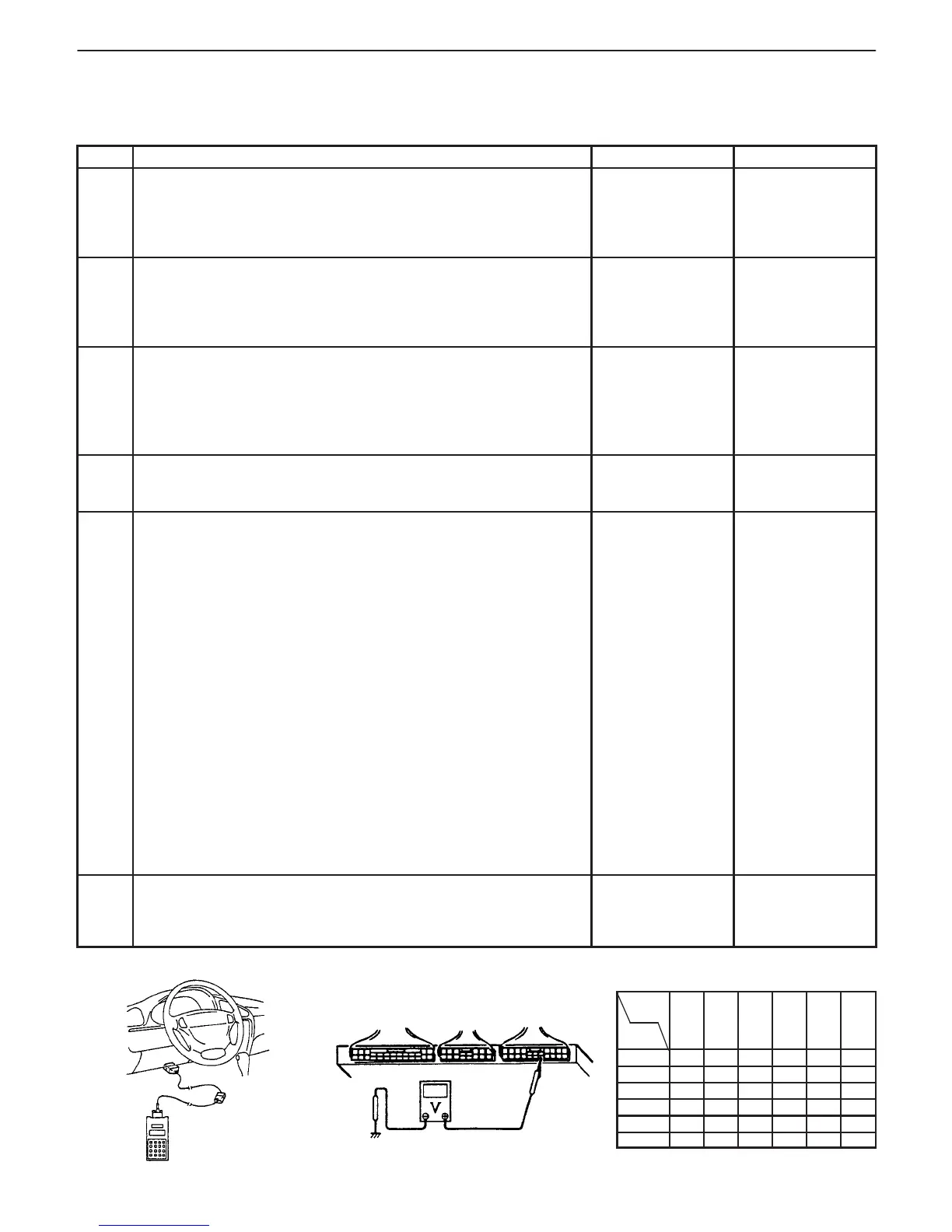
Fig. 1 for Step 5. Fig. 2 for Step 5. Fig. 3 for Step 5.
When not using SUZUKI
scan tool:
lever position
Terminal
Selector
AUTOMATIC TRANSMISSION BASIC CHECK
This check is very important for troubleshooting when PCM (ECM) has detected no DTC and no abnormality has
been found in visual inspection. Follow the flow table carefully.
STEP ACTION YES NO
1 Was “AUTOMATIC TRANSMISSION DIAG. FLOW TABLE”
performed?
Go to Step 2. Go to
“AUTOMATIC
TRANSMISSION
DIAG. FLOW
TABLE”.
2 Check A/T Fluid.
Warm transmission to normal operating temperature and check
fluid level and contamination referring to “FLUID LEVEL
CHECK” of “ON-VEHICLE SERVICE” in this section.
Is it in good condition?
Go to Step 3. Add or change
fluid.
3 Check Fluid Pressure Control Cable.
1) Warm up engine to normal operating temperature.
2) Check fluid pressure control cable for play referring to
“FLUID PRESSURE CONTROL CABLE” of “ON-VEHICLE
SERVICE” in this section.
Is it in good condition?
Go to Step 4. Adjust.
4 Check Select Cable for Adjustment referring to “SELECT
CABLE” of “ON-VEHICLE SERVICE” in this section.
Is it adjusted correctly?
Go to Step 5. Adjust.
5 Check Transmission Range Sensor (Switch) Circuit for
Operation.
When using SUZUKI scan tool:
1) Connect SUZUKI scan tool to DLC with ignition switch OFF.
2) Turn ignition switch ON and check transmission range
signal (P, R, N, D, 2 or L) on display when shifting manual
selector to each range. See Fig. 1.
Is applicable range indicated?
When not using SUZUKI scan tool:
1) Turn ignition switch ON.
,
C03-15 and C03-16 for G10 engine model (C02-11, C02-12,
C02-14, C02-15, C02-21 and C02-23 for G13 engine
model) respectively with selector lever shifted to each
range. See Fig. 2.
Taking terminal C03-3 for G10 engine model (C02-11 for
G13 engine model) as an example, is battery voltage
indicated only when selector lever is shifted to “2” range and
0 V for other ranges as shown in Fig. 3?
Check voltage at other terminals likewise, referring to Fig. 3.
Are check results satisfactory?
6 Check Engine Idle speed referring to Section 6E1 or 6E2.
Is it in good condition?
Go to
“SYMPTOM-TO-
INSPECTION
TABLE” below.
Go to Section
6E1 or 6E2.
C03-5
(C02-21)
C03-16
(C02-15)
C03-4
(C02-12)
C03-15
(C02-14)
C03-3
(C02-11)
C03-14
(C02-23)
P B + V 0 V 0 V 0 V 0 V 0 V
R 0 V B + V 0 V 0 V 0 V 0 V
N 0 V 0 V B + V 0 V 0 V 0 V
D 0 V 0 V 0 V B + V 0 V 0 V
2 0 V 0 V 0 V 0 V B + V 0 V
L 0 V 0 V 0 V 0 V 0 V B + V

 Loading...


