1. Countershaft gear
2. Output shaft speed sensor
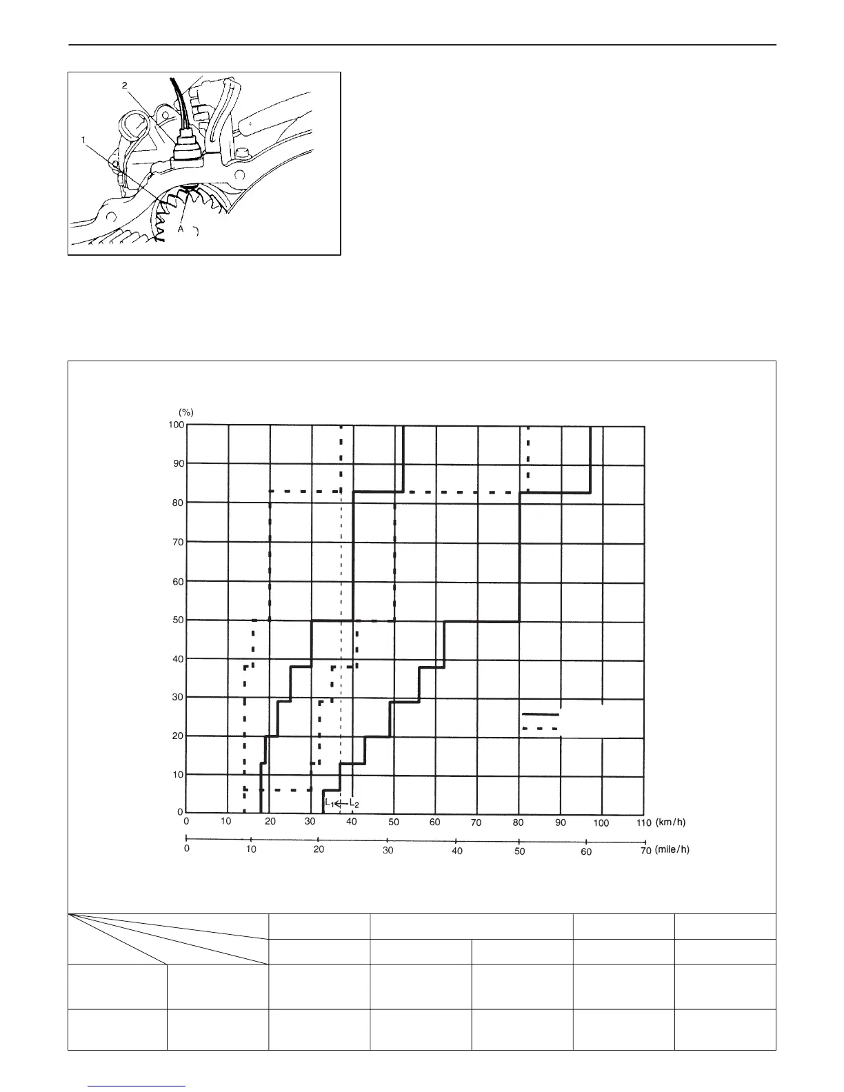
A: Magnetic core end
D or 2
1→2
18
11
52
33
D
2→3
33
21
97
61
3→2
14
9
82
51
D or 2
2→1
14
9
37
23
L
2→1
37
23
37
23
Full close
Full open
km/h
mile/h
km/h
mile/h
Throttle Speed
Gear
Selector
VEHICLE SPEED
Upshift
Downshift
THROTTLE VALVE OPENING
[G10 Engine Model]
AUTOMATIC TRANSMISSION (3 A / T) (VEHICLE WITH WU-TWC) 7B-9
OUTPUT SHAFT SPEED SENSOR (A/T VSS)
The output shaft speed sensor consists of a magnetic core with
magnet and coil. It is mounted on transmission case with 0.6 mm
(0.024 in.) air gap between the core end and countershaft gear
tooth.
While the countershaft rotates, magnetic flux is cut by gear tooth
thus a pulse is generated in the sensor coil according to the speed.
And then, the pulse is transmitted to engine control module as
speed signal.
AUTOMATIC SHIFT DIAGRAM
Automatic shift schedule as a result of shift control is shown below. In case that selector lever is shifted to L range
at a higher than 37 km/h (23 mile/h) (G10 engine model), 40 km/h (25 mile/h) (G13 engine model) speed, 2nd
gear is operated and then down shifts to 1st at a speed lower than that. No up shift is available in L range.

 Loading...


