6E1-12 ENGINE AND EMISSION CONTROL SYSTEM (TBI FOR G10)
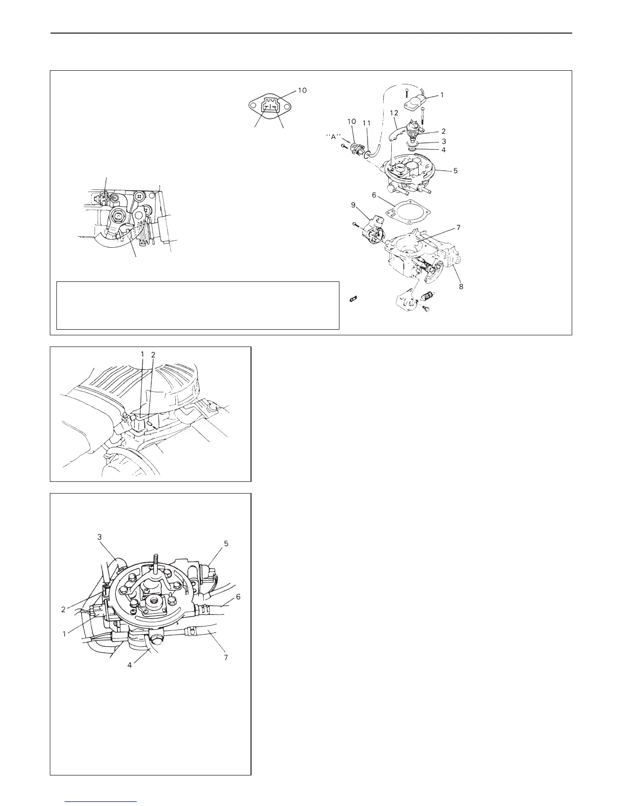
1. Fuel injector wire
2. Fuel injector
3. Upper O-ring
4. Lower O-ring
5. Throttle upper body
6. Gasket
7. Throttle lower body
8. ISC actuator
9. TP sensor
10. Injector sub wire coupler
11. O-ring
12. Injector wire cover
CAUTION:
As throttle stop screw and throttle lever screw are fac-
tory adjusted precisely, don’t remove or adjust them.
Throttle
stop
screw
Throttle lever
screw
Positive
terminal
Negative
terminal
Viewed from “A”
1. Throttle body
2. Vacuum nozzle
1. Injector coupler
2. TP sensor
3. Water hose
4. Vacuum hose
5. ISC actuator
6. Fuel return hose
7. Fuel feed hose
THROTTLE BODY
ON-VEHICLE INSPECTION
D Check that throttle valve lever moves smoothly.
D Vacuum passage inspection.
With fingers placed against vacuum nozzle, increase engine
speed a little and check that vacuum is applied.
REMOVAL
1) Relieve fuel pressure, referring to Section 6.
2) Disconnect battery negative cable at battery.
3) Remove air cleaner assembly referring to Section 6A.
4) Drain cooling system.
5) Disconnect following wire harness couplers:
D TP sensor
D Fuel injector
D ISC actuator
6) Disconnect following hoses from throttle body.
D Fuel feed and return hoses
D Engine cooling water hoses
D Vacuum hoses
7) Disconnect accelerator cable from throttle valve lever and cable
bracket.
8) Remove throttle body from intake manifold.

 Loading...


