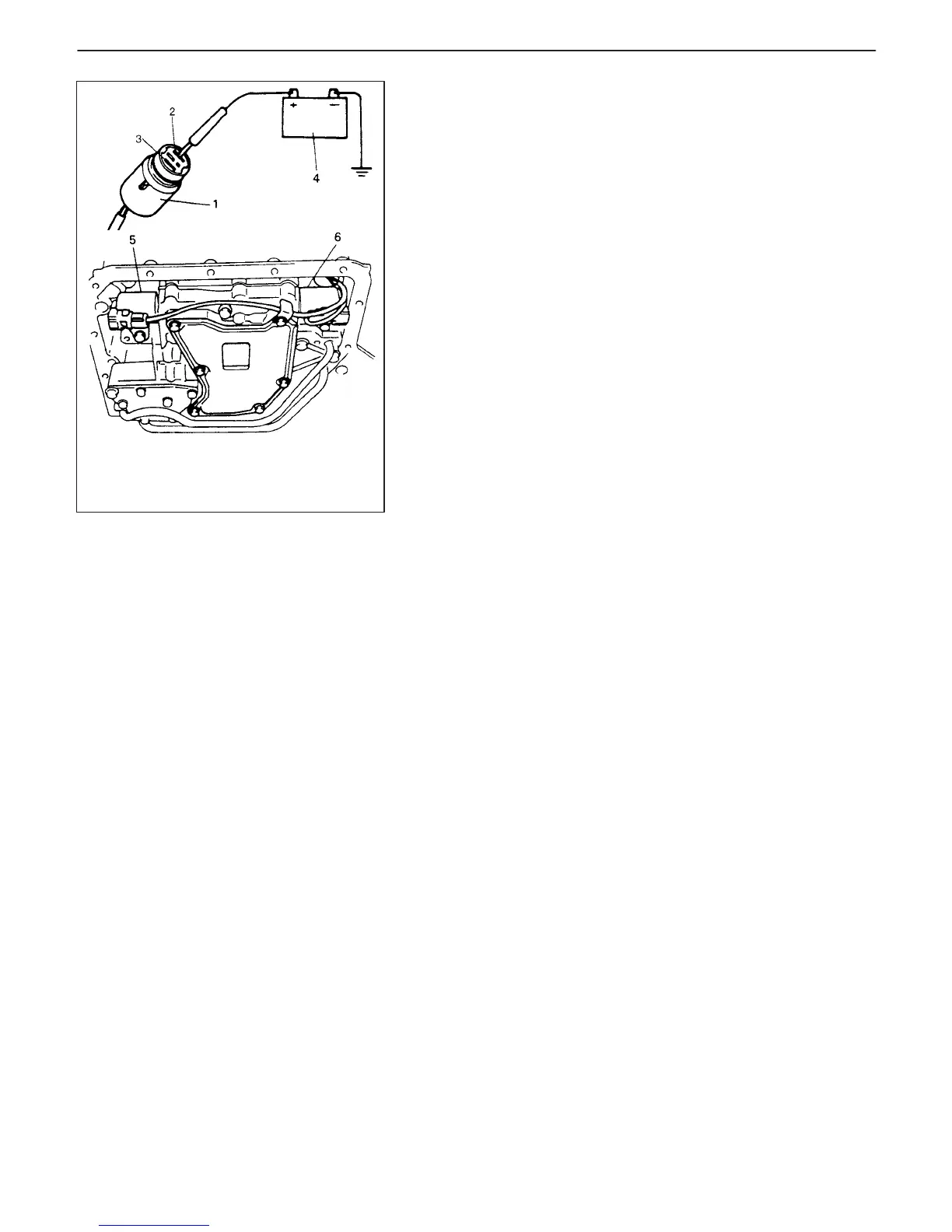
1. Solenoid valve wire coupler
2. Terminal for shift solenoid-A. (direct clutch solenoid)
3. Terminal for shift solenoid-B. (2nd brake solenoid)
4. 12 V battery
5. Shift solenoid-B. (2nd brake solenoid valve)
6. Shift solenoid-A. (Direct clutch solenoid valve)
AUTOMATIC TRANSMISSION (3 A / T) (VEHICLE WITH WU-TWC) 7B-41
3) Disconnect shift solenoid valve coupler from harness.
4) Apply 12 V to each terminal in solenoid valve coupler and check
to be sure that a click sound is heard from each of shift sole-
noid-A and -B.
If no click sound is heard, check lead wire and connections in oil
pan, and then replace applicable shift solenoid-A or B if wire and
connections are in good condition.
If click sound is heard from each of shift solenoids A and B, shift
solenoid electrical circuits are in good condition. Proceed to
“SHIFT SOLENOID VALVE CHECK” previously described in
this section.
THROTTLE POSITION SENSOR CHECK
Check throttle position sensor and its circuit referring to DTC P0121
Flow Table in Section 6 or 6-1.

 Loading...


