6-82 ENGINE GENERAL INFORMATION AND DIAGNOSIS (TBI FOR G10)
Vehicle speed
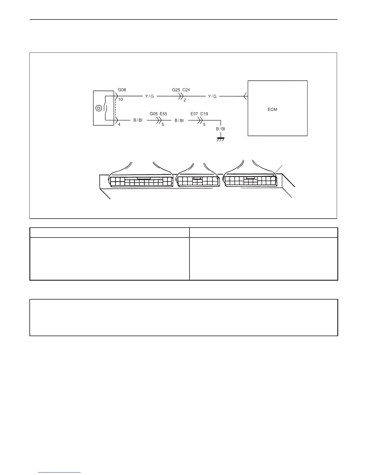
sensor in
combination meter
C03-2
C03-2
DTC P0500 VEHICLE SPEED SENSOR (VSS) MALFUNCTION (M/T)
CIRCUIT DESCRIPTION
DTC DETECTING CONDITION POSSIBLE CAUSE
D VSS signal not inputted while vehicle running in “D”
range or during fuel cut at deceleration.
: 2 driving cycle detection logic, continuous monitoring
D “B/Bl” circuit open
D “Y/G” circuit open or short
D VSS malfunction
D ECM malfunction
D Speedometer cable malfunction
DTC CONFIRMATION PROCEDURE
WARNING:
D When performing a road test, select a place where there is no traffic or possibility of a traffic accident
and be very careful during testing to avoid occurrence of an accident.
D Road test should be carried out with 2 persons, a driver and a tester.
1) Clear DTC and warm up engine to normal operating temperature.
2) Increase vehicle speed to 50 mph, 80 km/h in 3rd gear or “2” range while observing vehicle speed displayed
on scan tool.
3) Release accelerator pedal and with engine brake applied, keep vehicle coasting (fuel cut condition) for 4 sec.
or more.
4) Check pending DTC and DTC.

 Loading...


