ENGINE GENERAL INFORMATION AND DIAGNOSIS (TBI FOR G10) 6-55
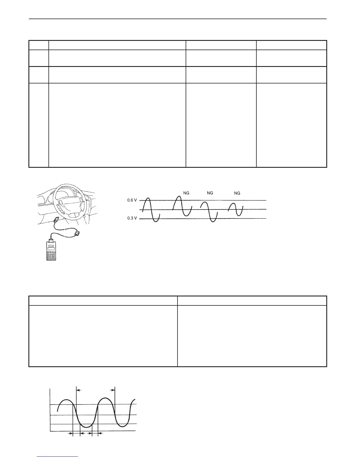
Fig. 1 for Step 3 Fig. 2 for Step 3
Normal
Fig. 1
HO2S-1
Output
voltage
1 cycle time
Response time
INSPECTION
STEP ACTION YES NO
1 Was “ENGINE DIAG. FLOW TABLE” performed? Go to Step 2. Go to “ENGINE DIAG.
FLOW TABLE”.
2 Is there DTC(s) other than HO2S-1
(DTC P0130)?
Go to applicable DTC
Diag. Flow Table.
Go to Step 3.
3 1) Connect scan tool to DLC with ignition switch
OFF.
2) Warm up engine to normal operating
temperature and keep it at 2000 r/min. for
60 sec.
3) Repeat racing engine (Repeat depressing
accelerator pedal 5 to 6 times continuously
and take foot off from pedal to enrich and
enlean A/F mixture). See Fig. 1 and 2.
Does HO2S-1 output voltage deflect between
0.3 V and over 0.6 V repeatedly?
Intermittent trouble.
Check for intermittent
referring to “Intermittent
and Poor Connection”
in Section 0A.
Check “R” and “G”
wires for open and
short, and connections
for poor connection.
If wires and connections
are OK, replace
HO2S-1.
DTC P0133 HEATED OXYGEN SENSOR (HO2S) CIRCUIT SLOW RESPONSE
(SENSOR-1)
WIRING DIAGRAM/CIRCUIT DESCRIPTION – Refer to DTC P0130 section.
DTC DETECTING CONDITION
POSSIBLE CAUSE
D When running at specified idle speed after engine
warmed up and running at specified vehicle speed,
response time (time to change from lean to rich or
from rich to lean) of HO2S-1 output voltage is about
1 sec. at minimum or average time of 1 cycle is 5 sec.
at minimum. See. Fig. 1
: 2 driving cycle detection logic, Monitoring once/1
driving.
D Heated oxygen sensor-1 malfunction

 Loading...


