2
IN
EX
(A)
1
ENGINE MECHANICAL (G13B, 1-CAM 16-VALVES ENGINE) 6A1-9
VALVE LASH (CLEARANCE)
1) Remove negative cable at battery.
2) Remove cylinder head cover referring to item “Cylinder Head
cover”.
3) Remove engine under cover of right side from body.
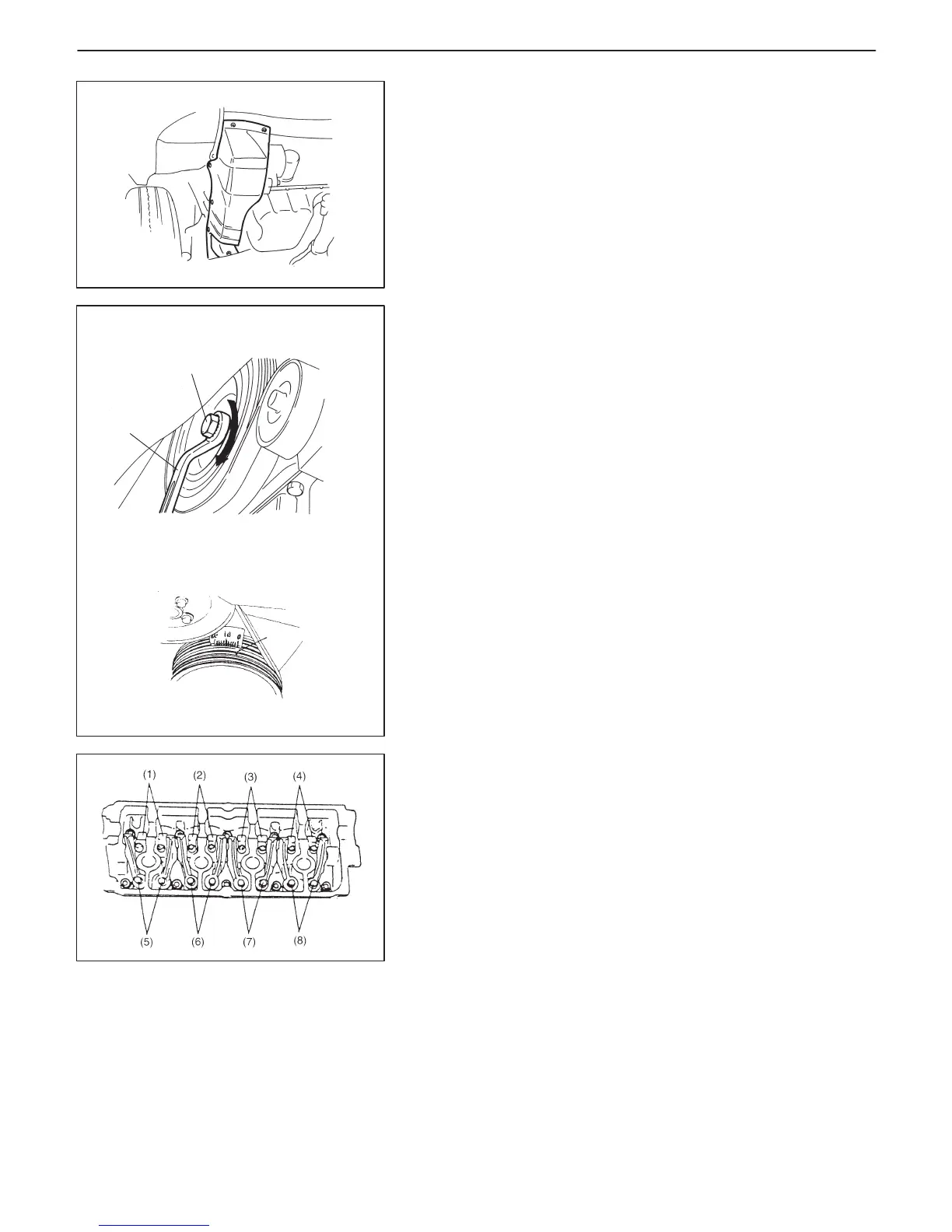
4) Using special tool and wrench (1), turn crankshaft pulley clock-
wise until “V” mark (2) (in white paint) on pulley aligns with “0”
(zero) calibrated on timing belt cover.
Special Tool
(A): 09919-16020
5) See if the rocker arms of No.1 cylinder are off the respective cam
lobes (of camshaft); if so, valves (1), (2), (5) and (7) in figure are
ready for clearance checking and adjustment. Check valve
lashes at valves (1), (2), (5) and (7).
If the rocker arms of No.4 cylinder are off the respective cam
lobes, check valve lashes at valves (3), (4), (6) and (8).
NOTE:
When checking valve clearance, insert thickness gauge be-
tween camshaft and cam-riding face of rocker arm.

 Loading...


