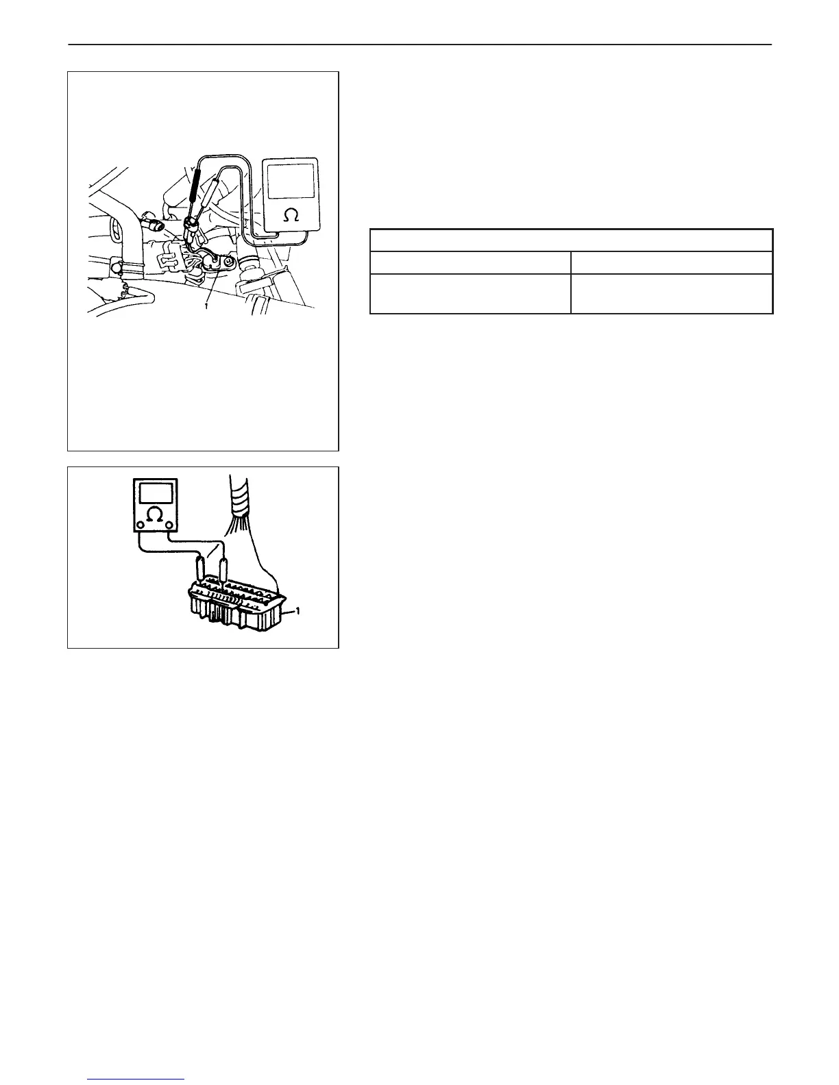
1. Output shaft speed sensor
1. PCM coupler disconnected
7B-40 AUTOMATIC TRANSMISSION (3 A / T) (VEHICLE WITH WU-TWC)
Separately from the above inspection, output shaft speed sensor
itself can be checked on its resistance by disconnecting coupler.
NOTE:
D Function of output shaft speed sensor can be checked by
measuring generated pulse as voltage.
D For its measurement, use an analog type voltmeter while
spinning wheels on lift and with selector lever in “D” range.
Output shaft speed sensor specifications
Coil resistance 100 – 300 Ω
Output voltage at 40 km/h
(25 mile/h)
Approximately 1 V
SHIFT SOLENOID VALVE CIRCUIT CHECK
1) With ignition switch turned OFF, disconnect PCM couplers.
2) Bring ohmmeter probes in touch with coupler terminals from har-
ness side and measure each resistance.
Resistance between C02-9 and C02-1
for G10 engine model (C03-4 and
C01-1 for G13 engine model)
(Shift solenoid-A, direct clutch) : 8 – 20 Ω
Resistance between C02-8 and C02-1
for G10 engine model (C03-11 and
C01-1 for G13 engine model)
(Shift solenoid-B, 2nd brake) : 8 – 20 Ω
If resistance is out of specification, check shift solenoid itself for
resistance (referring to Step 3 of DTC P0753/P0756 Flow Table)
and wire harness for open or short.
If resistance is within specification, proceed to step 3).

 Loading...


