4-6 SHB 28Z3 EN – Edition 2.0 * 28z3s410.fm
Engine
4.4 Checking and adjusting valve clearance
☞ The standard valve clearance setting is carried out on a cold engine:
➥ The firing order is 1 – 3 – 2, ignition at the 240 ° position of the crankshaft rotation.
Notice!
The first cylinder is located on the pump side at the flywheel end opposite the radi-
ator.
Checking valve clearance
☞ Remove the valve cover
☞ Turn the ring gear on the flywheel clockwise until the cylinder reaches top dead centre
of the compression cycle.
➥ Both rocker arms are accessible.
➥ The intake and exhaust valves can be set in this position.
➥ The top dead centre mark (indentation) can be seen on the flywheel.
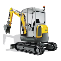
☞ Check the valve cap for abnormal wear – see Fig. 1.
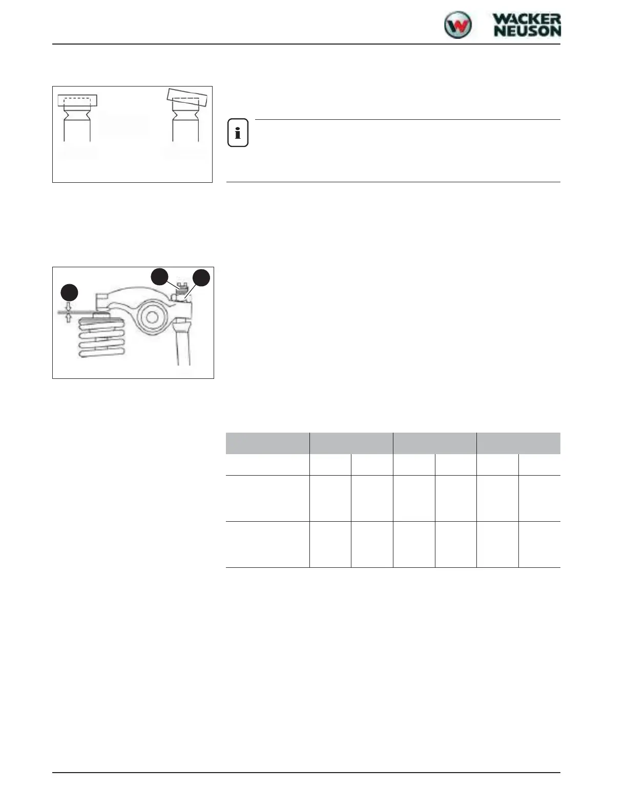
☞ Check valve clearance with feeler gauge A.
➥ Valve clearance: 0.15 – 0.25 mm (0.0059 – 0.0098”).
☞ Adjust the valve clearance if it varies.
To reduce the number of necessary rotations of the crankshaft for checking the valve
clearance, the setting of various valves can be adjusted in parallel in accordance with the
following table:
Example:
• Turn cylinder 1 to top dead centre (both valves closed – compression).
➥ The valves in the upper row of the table can be set in this manner.
• Then turn the crankshaft to top dead centre of the exhaust valve (only the exhaust
valve is open).
➥ Both other valves in the lower row of the table can be adjusted.
Setting valve clearance
☞ Check the valve setting as described in the “Valve clearance” section.
☞ Slacken locknut C and set screw B on the rocker arm.
☞ Check the valve cap for abnormal wear – see Fig. 1.
☞ For the correct valve clearance insert feeler gauge A.
Fig. 1: Valve cap wear
normal abnormal
Fig. 2: Valve clearance
A
B
C
Cylinder number 1 2 3
Valve Inlet Exhaust Inlet Exhaust Inlet Exhaust
Cylinder 1 at top
dead centre
(compression)
●●● ●
Cylinder 1 at top
dead centre
(exhaust open)
●●
 Loading...