5-6 SHB 28Z3 EN – Edition 2.0 * 28z3s510.fm
Hydraulic system
Dismantling the hydraulic pump
It is assumed that the hydraulic pump is only dismantled by staff who understand its inter-
nal construction.
Notice!
The seals and O-rings are probably damaged during dismantling and are therefore
unusable. Ensure that spare parts are ready for installation.
☞ Drain the oil, clean the pump and place on a clean rubber mat on a work bench
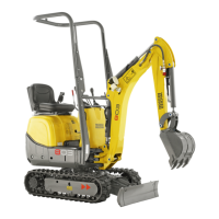
☞ Unscrew the hexagon socket screws (3 x) and remove the pilot oil supply unit
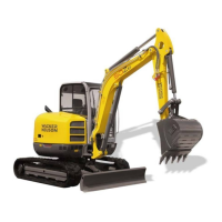
☞ Unscrew the hexagon head screws (2 x) and remove the gear pump and coupling with
the ring
➥ The coupling and ring are located either on the gear pump or variable displacement
pump
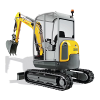
☞ Mark or measure the setting of the set screw and note
➥ Makes it easier to restore the correct pump setting
☞ Slacken the locknut and unscrew the set screw with an Allen key
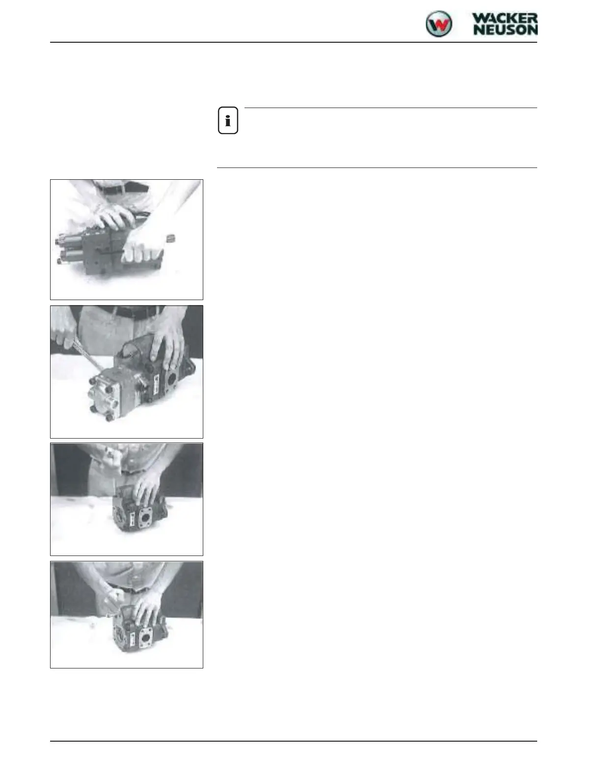
☞ Unscrew the hexagon socket screws (5 x) and separate the pump housing
➥ The housing can be separated more easily by tapping the housing with the inside
spring lightly by means of a rubber hammer
☞ Remove the intermediate seal
Fig. 1: Removing the pilot oil supply unit
Fig. 2: Removing the gear pump
Fig. 3: Removing the set screw
Fig. 4: Separating the housing
 Loading...