5-20 SHB 28Z3 EN – Edition 2.0 * 28z3s510.fm
Hydraulic system
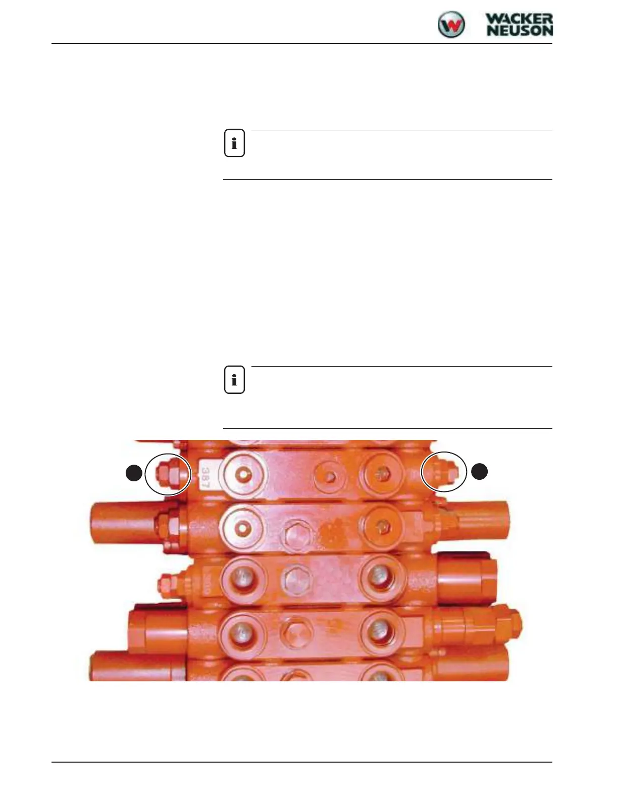
5.6 Auxiliary hydraulics flow rate adjustment
The available oil quantity at the auxiliary hydraulics ports can be modified by means of set
screws A or B on the main valve block.
Set screw – see Pressure limiting valves on page 5-16
Notice!
Open both set screws to achieve the effect described below.
There are two possible positions:
Set screw “against hydraulic resistance”
The valve seat is closed in this position
• P2 + P3 supply the auxiliary hydraulics section with oil
• Factory setting
“Open” set screw
Unscrew the valve seat by at least 2 revolutions, but no more than 3, to open the valve
seat completely.
• P2 supplies the auxiliary hydraulics section with oil
• The oil supplied by P3 flows to the tank via the open valve seat.
Notice!
Intermediate positions of the set screws cause the hydraulic oil to warm up – dan-
ger of overheating!
A
B

 Loading...