4-10 SHB 28Z3 EN – Edition 2.0 * 28z3s410.fm
Engine
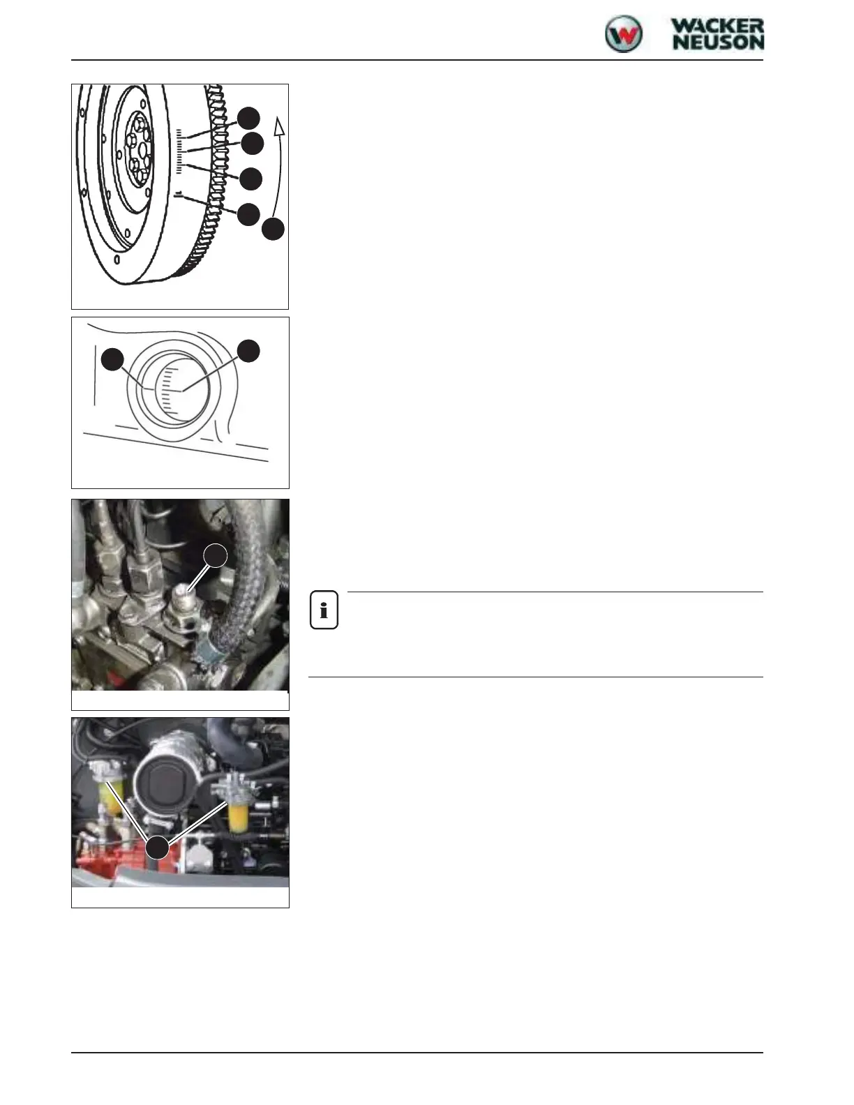
Marks (standard specification) on the flywheel:
• 6/A top dead centre with corresponding cylinder number
• 6/B 15° before top dead centre
• 6/C 20° before top dead centre
• 6/D 25° before top dead centre
• 6/E direction of rotation
☞ Turn until mark 7/G on the ring gear for cylinder 1 is visible and at the same level as
mark 7/F on the flywheel housing
➥ Rated injection point 16° before top dead centre (+/- 1°)
☞ Mark the (rated) injection point on the flywheel housing and ring gear
Measurement:
☞ Slacken the high-pressure fuel injection lines of cylinder 1 and push to one side
➥ The opening of injection pump A must be visible
☞ Open all fuel cocks B, see Fig. 10
Notice!
Fuel is pumped to the cylinder only every second turn of the crankshaft; for this
reason it may be necessary to turn the crankshaft twice.
☞ An auxiliary means (fuel injection line with a transparent pipe) can be mounted on the
fuel injection line for precise observation – see Fig. 10
➥ This auxiliary means is not essential
☞ Position a spanner on the screw of the pulley (on the crankshaft)
➥ Or turn the ring gear on the flywheel with a screwdriver
☞ Slowly turn clockwise until fuel is discharged from the opening of injection pump A
Fig. 6: Marks on flywheel
D
C
B
A
E
Fig. 7: Mark before top dead centre
G
F
Fig. 8: Opening on fuel pump
A
Fig. 10: Turning the fuel cocks to flow
B

 Loading...