
Do you have a question about the Xerox Phaser 4600 and is the answer not in the manual?
| Print Technology | Laser |
|---|---|
| Print Resolution | Up to 1200 x 1200 dpi |
| Monthly Duty Cycle | Up to 275, 000 pages |
| Maximum Paper Capacity | 3, 750 sheets |
| Processor | 533 MHz |
| Supported Operating Systems | Windows, Mac OS, Linux |
| Connectivity | USB 2.0, Ethernet 10/100/1000Base-T |
| Memory | 256 MB |
| Maximum Paper Size | 8.5 x 14 inches |
| Print Languages | PCL 6, PostScript 3 |
| Duplex Printing | Standard |
| Weight | 25.9 kg |
Provides details on the manual's purpose, organization, and how to use it effectively.
Guides users on the systematic approach to troubleshooting and service call procedures.
Outlines essential safety guidelines, warnings, and precautions for servicing the printer.
Explains precautionary symbols found on the machine to ensure user safety.
Details DC and AC voltage measurements, logic levels, and specifications for diagnostics.
Defines requirements for reporting health and safety incidents involving Xerox products.
Covers electromagnetic emission and immunity standards, including FCC and Canadian regulations.
Provides warnings in multiple languages for international safety compliance.
Illustrates and labels the components visible on the front of the printer.
Illustrates and labels the components located at the rear of the printer.
Details features enabled by Hard Drive installation, such as Secure Print and Disk Collation.
Specifies memory upgrade requirements, including DDR2 DIMM characteristics.
Explains how the 520-sheet feeder increases input capacity and supported tray combinations.
Describes the 2000-sheet feeder's function and supported tray combinations.
Details the Mailbox's function of sorting prints into four 100-sheet output trays.
Explains the Finisher's capabilities, including stapling and job stacking with offset.
Lists consumable items and their print life expectancy, including toner and drum cartridges.
Gathers initial information about the machine's performance and the reported problem.
Outlines procedures specific to the first service call for a machine.
Details steps to determine the reason for a service call.
Provides guidance on identifying faults using fault codes, UI issues, and image quality defects.
Contains information regarding component life and maintenance for various subsystems.
Evaluates the total operation of the system and identifies actions required to complete the service call.
Details the printer's configurations and available options for different models.
Provides troubleshooting steps for the Top Door Open error.
Provides troubleshooting steps for the Rear Door Open error.
Troubleshooting steps for the Finisher Door Open error.
Troubleshooting steps for the Staple Cartridge Door Open error.
Addresses communication errors between the MCU Board and Tray 3.
Troubleshooting steps when Tray 2 media size settings differ from the size switch.
Addresses memory access failures detected within the Network Controller.
Troubleshooting steps when the Tray 2 Stack Height Sensor state does not change.
Addresses errors occurring in the Main Drive Assembly.
Troubleshooting steps when Tray 2 is indicated as empty by the No Paper Sensor.
Troubleshooting steps for media jams at the Tray 2 Take Away Sensor.
Addresses media jams in the Registration Rollers.
Troubleshooting steps for media remaining in the Tray 2 Pick-up Assembly.
Addresses situations where toner is almost empty or unevenly distributed.
Troubleshooting steps when the Toner Cartridge has reached its end of life.
Addresses situations where the Waste Toner Cartridge is near end of life.
Troubleshooting steps when the Waste Toner Cartridge Detect Sensor indicates it's not installed.
Covers errors related to Fuser temperature, including open circuit and overheat conditions.
Troubleshooting steps when the Fuser Drive Assembly fails to rotate.
Addresses media jams at the Finisher entrance.
Troubleshooting steps when the Stack Full Sensor indicates the Finisher Stacker Tray is full.
Addresses situations where the Staple Cartridge is near empty.
Troubleshooting steps when the left tamper does not move from or to home position.
Troubleshooting steps when the stapler fails or the jaw does not move to home position.
Addresses media jams at the Mailbox entrance.
Indicates when a Mailbox bin is full.
Troubleshooting steps for jams within the Mailbox bins.
Addresses faults with the Finisher IOT exit gate diverter.
Troubleshooting communication or network failures during SMTP or LDAP operations.
Addresses issues when two devices attempt to use the same IP address.
Troubleshooting steps when the network cable is not connected.
Establishes the source and type of imaging defects for effective troubleshooting.
Provides procedures to correct defects appearing as missing image areas.
Addresses issues where the printed image is not fully fused to the paper.
Details how to check image resolution by inspecting pixel lines and halftone patches.
Addresses image positioning issues where the image is not parallel to the print sheet edge.
Troubleshooting steps for prints with overall light image density.
Addresses randomly scattered toner spots on the page.
Troubleshooting steps for output with no visible image.
Addresses prints that are completely black with no visible image.
Troubleshooting extraneous vertical dark lines or bands on prints.
Addresses black lines running horizontally across the page.
Troubleshooting pages that are wrinkled, creased, or torn.
Addresses recurring marks, spots, lines, or voids in the print.
Troubleshooting issues where a previous image appears on the current print.
Addresses toner contamination appearing as a light gray dusting.
Troubleshooting image density variations across the page.
Addresses stains on the non-image side of printed sheets.
Troubleshooting image positioning errors in process or scan direction.
Addresses printing issues where vertical lines are not straight.
Describes test patterns used for identifying image quality defects.
Details specifications and procedures for checking solid area density on test prints.
Addresses issues related to image skew and provides margin specifications.
Details specifications and procedures for checking image registration.
Provides specifications for using transparency media.
Details the guaranteed printing area specifications for the printer.
Provides removal instructions for the Fuser Drive Board.
Provides removal instructions for the Fuser Drive Board Assembly.
Details the removal procedure for the High Voltage Power Supply (HVPS).
Details the removal procedure for the Switched Mode Power Supply (SMPS).
Provides removal instructions for the Top/Rear Door Interlock Switch.
Details the removal procedure for the SMPS Fan.
Outlines the steps for removing the Control Panel Assembly.
Provides instructions for removing the Control Panel Board.
Details the removal procedure for the MCU Board.
Provides instructions for removing the IP Board Cage.
Outlines the procedure for removing the IP Board.
Details the removal procedure for the Main Drive Assembly.
Provides instructions for removing the Tray 2 Feed Clutch.
Outlines the procedure for removing the Registration Clutch.
Details the removal procedure for the Feed Drive Assembly.
Provides instructions for removing the Right Side Chassis Fan.
Details the removal procedure for the Laser Unit.
Outlines the steps for removing the Tray 1 Feeder Assembly.
Provides instructions for removing the Tray 1 Pick-up Assembly.
Details the removal procedure for the Tray 1 Separator Assembly.
Outlines the steps for removing the Tray 2 Feeder Assembly.
Provides removal instructions for the Tray 2 Lift Motor.
Details the removal procedure for the Tray 2 Lift Gear.
Outlines the steps for removing the Tray 1 No Paper Sensor.
Provides instructions for removing the Tray 1 Feed Clutch.
Details the removal procedure for the Tray Separator Roller.
Outlines the steps for removing the Tray Separator Clutch.
Provides instructions for removing the Tray Front Cover.
Details the removal procedure for the Tray Media Level Indicator.
Outlines the steps for removing the Feeder Front Cover.
Provides instructions for removing the Feeder Right Cover.
Details the removal procedure for the Feeder Left Cover.
Outlines the steps for removing the Feeder Rear Cover.
Provides instructions for removing the Feeder Board.
Details the removal procedure for the Feeder Lift Motor.
Outlines the steps for removing the Feeder Size Switch.
Provides instructions for removing the Upper Option Harness.
Details the removal procedure for the Lower Option Harness.
Outlines the steps for removing the Left Side Frame.
Provides instructions for removing the Right Side Frame.
Details the removal procedure for the Feeder No Paper Sensor.
Outlines the steps for removing the Feeder No Paper Sensor Actuator.
Provides instructions for removing the Feeder Stack Height Sensor.
Details the removal procedure for the HCF Rear Cover.
Outlines the steps for removing the HCF Right Cover.
Provides instructions for removing the HCF Left Cover.
Details the removal procedure for the HCF Caster.
Outlines the steps for removing the HCF Reduction Gear Assembly.
Provides instructions for removing the HCF Front Door Interlock Switch.
Details the removal procedure for the HCF Control Board.
Outlines the steps for removing the HCF Lift Motor Assembly.
Provides instructions for removing the HCF Feed Clutch.
Details the removal procedure for the HCF Feed Drive Assembly.
Outlines the steps for removing the HCF Feed Motor.
Provides instructions for removing the HCF Top Plate.
Details the removal procedure for the Registration Sensor.
Outlines the steps for removing the Feed Sensor.
Provides instructions for removing the Shaft Frame Assembly.
Details the removal procedure for the Drum Cartridge CRUM Connector.
Outlines the steps for removing the Registration Roller Assembly.
Provides instructions for removing the Registration Sensor Actuator.
Details the removal procedure for the Feed Sensor Actuator.
Outlines the steps for removing the Feeder Take Away Clutch.
Provides instructions for removing the Feeder Feed Clutch.
Details the removal procedure for the Feeder Feed Drive Assembly.
Outlines the steps for removing the Feeder Take Away Sensor Actuator.
Provides instructions for removing the Feeder Take Away Sensor.
Details the removal procedure for the Feeder Take Away Roller.
Outlines the steps for removing the Feeder Feed Assembly.
Provides instructions for removing the HCF Feed Assembly.
Details the parts for the High Voltage Power Supply (HVPS) and Switched Mode Power Supply (SMPS).
Lists parts associated with the Fuser Drive Board Assembly.
Details the components of the Control Panel assembly.
Lists the main Printed Wiring Boards (PWBs) including MCU and IP boards.
Details parts related to the printer's main drive assemblies, motors, and clutches.
Lists the parts for the Laser Unit, including laser diodes and scanner components.
Details parts for Paper Trays, including guides, rollers, and sensors.
Lists main covers and frames for optional feeders.
Details covers and assemblies for the High Capacity Feeder (HCF).
Provides an exploded view and parts list for the High Capacity Feeder (HCF) assembly.
Lists components for the Tray 1 Feeder Assembly, including rollers and sensors.
Details parts for the Tray 2 Pick-up Assembly, including sensors and rollers.
Lists components for optional feeder pick-up assemblies.
Details parts for optional feeder main drives, motors, and clutches.
Lists components for the optional feeder lift assembly.
Details parts for the optional feeder feed assembly.
Lists components for the Registration Roller Assembly.
Details parts for the middle frame assembly.
Lists components for the upper frame assembly.
Details toner and drum cartridges, including part numbers and capacities.
Lists parts related to the waste toner system, including sensors and cartridges.
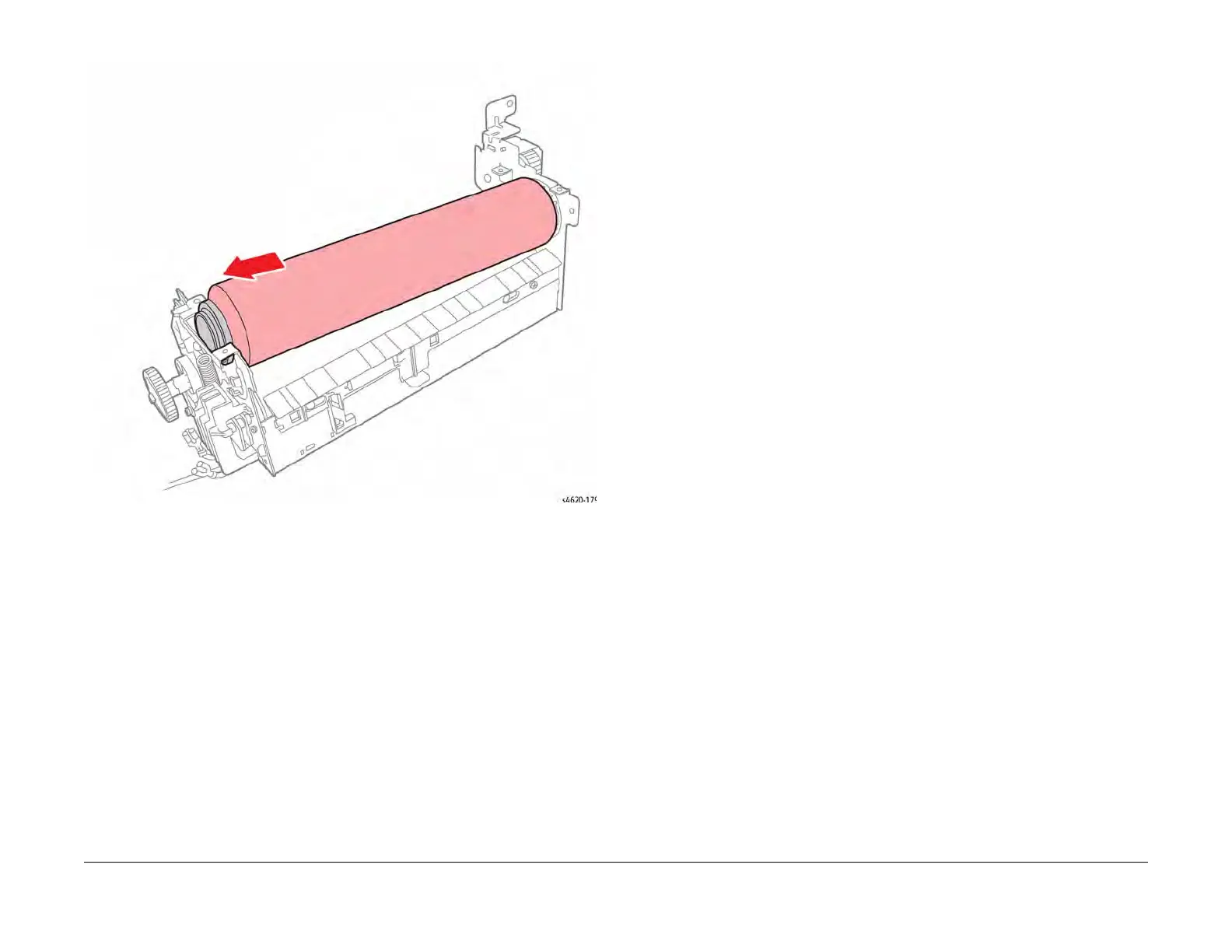
Details parts for the Fuser Assembly, including heat and pressure components.
Continues the parts list for the Fuser Assembly, detailing rollers, gears, and lamps.
Lists parts for the Upper Fuser Bracket Assembly, including thermistors.
Details parts for the Lower Fuser Exit Guide Assembly.
Lists components of the Duplex Unit Assembly.
Details parts for the Exit Assembly, including rollers and sensors.
Lists covers and external parts for the Mailbox.
Details the Mailbox Control Board and associated brackets.
Lists parts for the Mailbox Drive Belts and transport motor.
Details components of the Mailbox Diverter Assembly.
Lists parts for the Mailbox Top Stacker Assembly.
Details components of the Mailbox Actuator Shield Assembly.
Lists parts for the Mailbox Base Assembly.
Details covers and external parts for the Finisher.
Lists parts for the Finisher Control Board.
Details components of the Finisher Stacker Shield Assembly.
Lists parts for the Finisher Stacker Drive Assembly.
Details components of the Finisher Compile Tray Eject Assembly.
Lists parts for the Finisher Compile Tray Assembly.
Details components of the Finisher Transport Drive Assembly.
Lists parts for the Finisher Stapler Assembly.
Details covers and external parts of the printer.
Lists components for the Top Cover Assembly.
Details parts for the Front Cover Assembly.
Lists components of the Rear Door Assembly.
Lists printer supplies and customer replaceable units, including toner and maintenance kits.
Details how to enter and exit the printer's diagnostic mode.
Explains how to access and interpret fault history information and error codes.
Covers tools for managing printer settings, including paper, jobs, and network configurations.
Lists available reports from the printer's control panel, such as Configuration and Supplies Usage.
Provides procedures for upgrading system firmware via remote or local methods.
Outlines techniques to prevent component damage caused by static electricity.
Lists functional and electrical specifications for the printer.
Provides essential precautions to follow when disassembling and reassembling components.
Illustrates the structure of the service menu for accessing various diagnostic functions.
Details procedures for checking the operation and diagnosing faults of printer motors.
Provides guidance on checking the operation of various printer sensors.
Outlines procedures for checking the functionality of clutches and solenoids.
Details how to check the operation of various printer switches, including interlocks.
Describes procedures for removing Mailbox or Finisher modules from the printer.
Provides safety guidelines and techniques for lifting and moving heavy printer modules.
Gives information on the correct use and application of lubricants.
Specifies the required clearances and environmental conditions for printer installation.
Provides definitions for technical terms, acronyms, and abbreviations used in the manual.
Information on RoHS Directive restrictions for hazardous substances in electronic equipment.
Defines First Print Output Time (FPOT) and provides specifications for ready and sleep states.
Lists paper and media specifications, including types that may damage the printer.
Provides environmental specifications for printer operation and storage.
Details how to review and modify machine configuration and control parameters stored in NVM.
Provides instructions to reset NVRAM to factory default settings.
Describes how to test the Control Panel display function.
Explains how to check input component status and energize output components for testing.
Guides users on printing embedded test patterns for troubleshooting image quality issues.
Provides the system diagram for the IOT (Input/Output Terminal).
Illustrates the interface connections for the IP Board.
Shows the MCU Board connections, part 1 of 4.
Illustrates the MCU Board connections, part 2 of 4.
Shows the MCU Board connections, part 3 of 4.
Illustrates the MCU Board connections, part 4 of 4.
Shows the Joint Board connections, part 1 of 2.
Illustrates the Joint Board connections, part 2 of 2.
Shows the IP Board connections, part 1 of 2.
Illustrates the Laser Unit connections.
Shows the High Voltage Power Supply (HVPS) connections.
Illustrates the Switched Mode Power Supply (SMPS) connections.
Shows the system diagram for the 500-Sheet Feeder.
Illustrates the Feeder Board connections for the 500-Sheet Feeder, part 1/2.
Shows the 500-Sheet Feeder Board connections, part 2/2.
Illustrates the system diagram for the 2000-Sheet Feeder.
Shows the system diagram for the Finisher.
Illustrates the system diagram for the Mailbox.
Provides a detailed description of the printer's operational characteristics and major assemblies.
Explains how media is driven through the printer via motors, belts, and sensors.
Describes various sensor types used for paper path tracking, jam detection, and component monitoring.
Explains the xerographic process, including the Drum Cartridge and its components.
Details components of the printer, including Trays, Duplex Unit, Exit Assembly, and Drive Systems.
Describes optional features like feeders, mailbox, and finisher, detailing their paper path and components.
Explains how media size is set using guides and the bottom plate for feeding.
Details the feeder mechanism and its driving components.
Lists drive and electrical components for the 520-Sheet Feeder, including the Feed Drive Assembly.
Describes sensors for No Paper, Stack Height, Take Away, and Size detection.
Monitors Mailbox status and media location, including entrance, stack full, and tray empty sensors.
Details components for driving media transport and activating exit gates and diverters.
Responsible for all Mailbox functions, receiving signals from the MCU Board.
Describes the media path components within the Finisher, from printer exit to stacker.
Lists and describes sensors like Exit Gate, Entrance, Exit, and Stacker Full.
Assembles and aligns media edges for stapling, and offsets stapled sets.
Aligns media edges using tamper motors, occurring each time a sheet reaches the Compiler Tray.
Shifts paper position as sets are ejected to the Stacker Tray to prevent jams.
Details sensors and motors for the Compile Tray, including tamper and eject functions.
Limits media sheets to prevent Stapler damage; ejects excess sheets.
Describes sensors for low staple count, staple cartridge status, and staple home position.
Discusses the Stacker Tray's position adjustment based on sensors and its components.
Describes interlock switches that block finisher motor power or indicate jams.


