04/2016
6-29
Phaser 4600/4620/4622 Printer Service Manual
dC305, dC330
6 General Procedures and Information
Revised
dC305 UI Test
Purpose
To test Control panel display function.
1. Enter diagnostics, refer to GP 1.
2. Select Printer Routines, the DC305 NVRAM Initialization.
3. Select from LDCD test or a complete UI test.
The display turns black as data is written to the display buffer. For the complete test, following
the LCD test, the test continues prompting for each Control Panel button.
dC330 Component Control
Purpose
To show the status of input components e.g. sensors, and to energize output components e.g.
motors, solenoids.
Description
Output and input component codes are entered into the Component Control Table on the Con-
trol Panel, and then energized individually or in permitted groups. The codes in the tables are
grouped in similar functional behavior.
NOTE: Test display names do not necessarily match part names used in this manual. Where
possible, test descriptions identify the part as named in the manual.
Go to the appropriate procedure:
• Input Components
• Output Components
Input Components
When the appropriate code is entered, component status appears on the Control Panel.
NOTE: The actual signal as measured with a service meter will not necessarily be the same as
the logic state shown on the Control Panel, especially where the output is inverted. When test-
ing components using these control codes, look for a change in state, not for a high or low.
The displayed status of the input component can be changed by causing the component status
to change, e.g. operating a sensor with a sheet of paper.
Go to the appropriate table:
• Table 1 Input Codes 01 IOT Interlocks
• Table 2 Input Codes 04 Main Drive Assembly
• Table 3 Input Codes 06 Laser Unit
• Table 4 Input Codes 07 Tray and size sensors
• Table 5 Input Codes 08 Media path sensors
• Table 6 Input Codes 09 Developer bias voltages
• Table 7 Input Codes 10 Fuser
• Table 8 Input Codes 12 Finisher / Mailbox
NOTE: Mailbox output trays are numbered 1 through 4 with 4 being the top tray.
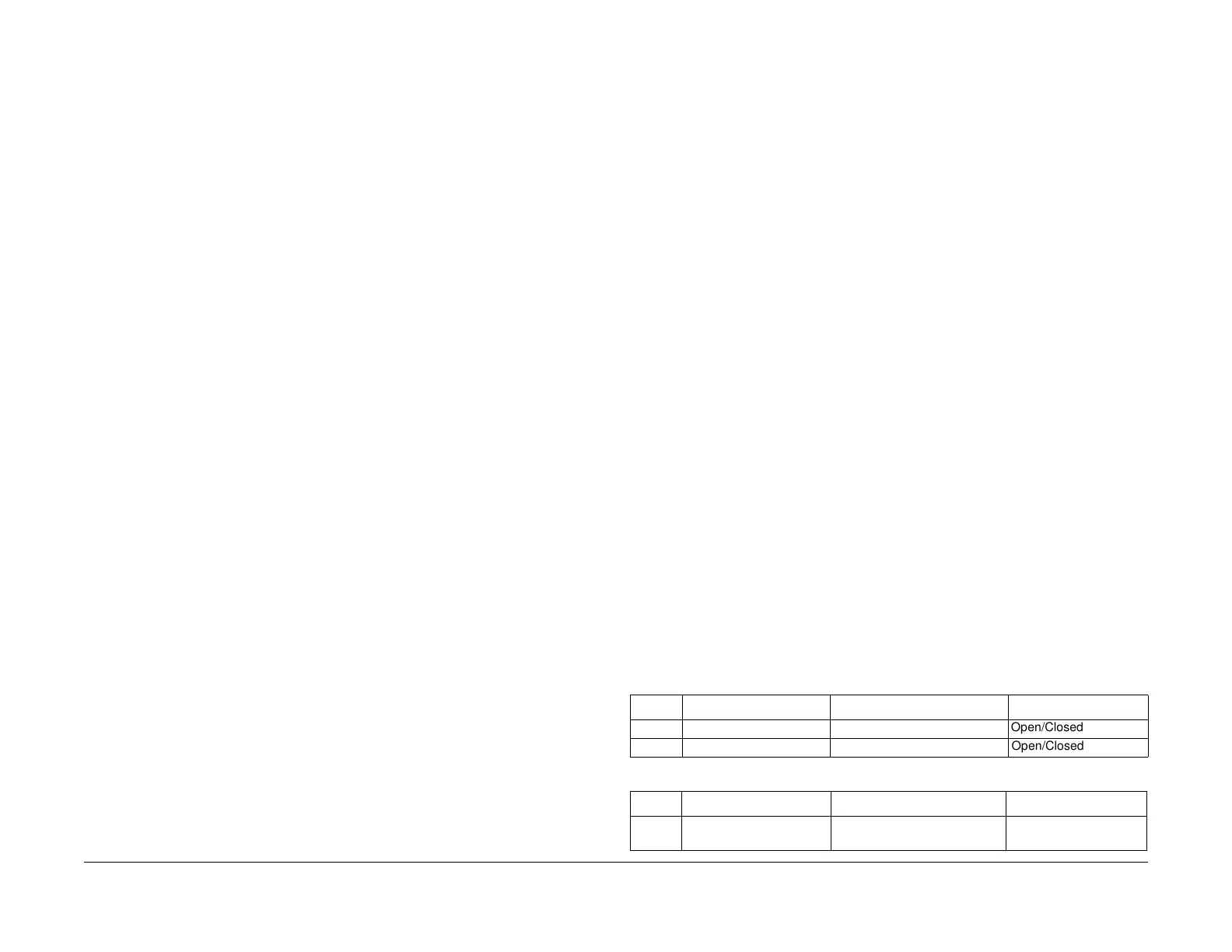
Table 1 Input Codes 01
Code Display Name Description General
01-100 Top/Rear Door Open Top/Rear Door Interlock Switch Open/Closed
01-300 Top/Rear Door Open Top/Rear Door connection Open/Closed
Table 2 Input Codes 04
Code Display Name Description General
04-110 Main BLDC Motor Ready High = normal speed
Low = abnormal speed
 Loading...


