04/2016
6-12
Phaser 4600/4620/4622 Printer Service Manual
GP 10, GP 11
Revised
6 General Procedures and Information
2. Check that the drive voltage at the driver PWB when the component control code for the
motor is entered. If the drive voltage is present, check the wiring and connectors to the
motor. If the drive voltage is not present, check the power to the driver PWB. If the power
to the PWB is good, install a new driver PWB.
NOTE: When checking for pulses, use a standard digital multimeter. Using the DC volts range,
or the AC volts range, expect to obtain a reading greater than 1V and less than 4 volts, while
the motor is running. The actual value depends on the meter’s reaction to square waves and to
the particular frequency of the pulses. It is common to obtain a reading of 2 to 3 volts. If the
meter has a minimum and maximum recording facility, expect a maximum value of around +4.9
volts DC, and a minimum value of around +0.2 volts DC
Check the operation of the encoder as follows:
Check for pulses when the motor is running. If pulses are present, check the driver PWB. If
pulses are not present at the motor, check the wiring to the motor and repair to install new wir-
ing. If pulses are present, install a new driver PWB.
Four Wire Stepper Motor
NOTE: A stepper motor with an internal open circuit may appear to be fully functional under
dC330 component control. However, under normal operation it will run with intermittent failure.
Use the multimeter to check stepper motor coil resistance is similar.
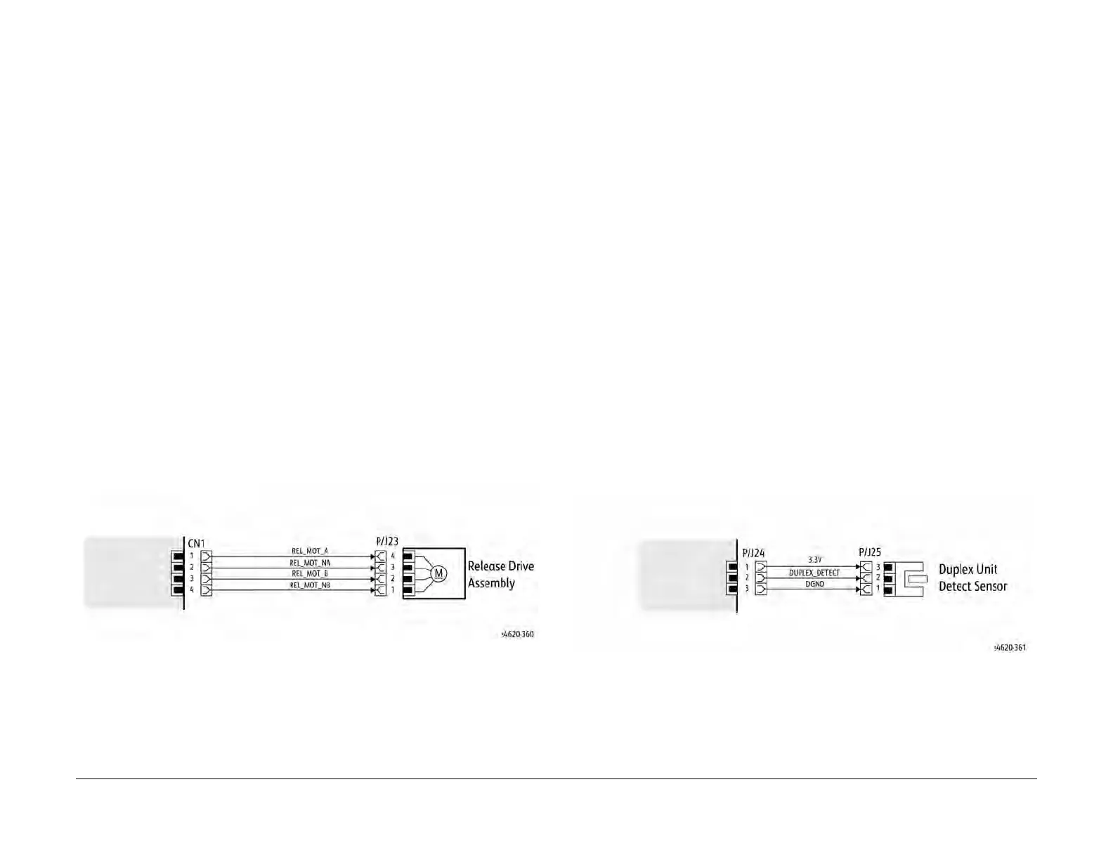
1. Refer to Figure 1. Disconnect PJ23. Check the +24V supply and the phase pulses to
GND when the component control code for the motor is entered. If the supply and pulses
are present, install a new motor.
2. Check the connectors and wiring to the motor. Repair or install new wiring, as necessary.
3. Disconnect CN1. Check the +24V. If +24V is not present, check the power to the PWB. If
the power is good, install a new PWB. Check the phase pulses at the PWB. If the phase
pulses are not present at the PWB, install a new PWB
Figure 1 Example Motor Wiring Diagram
GP 11 How to Check a Sensor
Use this procedure to check the operation of all types of sensor.
NOTE: Some sensors have a resistor within the sensor and other sensors require a resistor on
the PWB. The resistor limits the current through the LED. The voltage to the sensor LED with
an external resistor, is typically 1.2V.
NOTE: The voltages, PJ numbers, pin numbers and PWB names shown are examples only.
Go to the wiring diagram associated with the RAP for the correct information.
NOTE: In some cases, two sensors are used to form an interruptible beam of light. In these
cases, the LED of one sensor and the sensing element of the other sensor are used. Treat the
two sensors as if they were housed in the same body for diagnostic purposes, ignoring the
unused part of each sensor. If the combined sensors do not operate correctly and the beam
path is clear of obstruction, it may be necessary to install both new sensors.
Quick Sensor Check
Enter the component control code for the sensor, refer to dC330. Actuate the sensor. If the dis-
play changes, the sensor operates correctly. If the display does not change, perform the proce-
dure.
Procedure
For the sensor in the wiring diagram shown in Figure 1:
1. Actuate the sensor and check for a change in voltage at PJ24, pin 2. If the voltage
changes, install a new PWB. If the voltage does not change, continue to the next step.
2. Disconnect PJ25. Check for +3.3V and 0V (GND) on the harness.
3. Disconnect PJ24 and PJ25. Check the harness and the connectors for continuity.
4. Check for +3.3V and 0V (GND) at the PWB.
5. If necessary, install new components or repair the wiring.
Figure 1 Example Sensor Wiring Diagram
 Loading...


