Connection
Chapter 5
53
1SFC132003M0201
5:2.2.7 Programmable output relay K6,
terminals 18, 19, and 20
The output relay gives signal depending on the selected
function.
Default: Event
See Chapter 7 “Settings and configuration” for programming.
1. Connect the cables to terminal 18, 19, and 20.
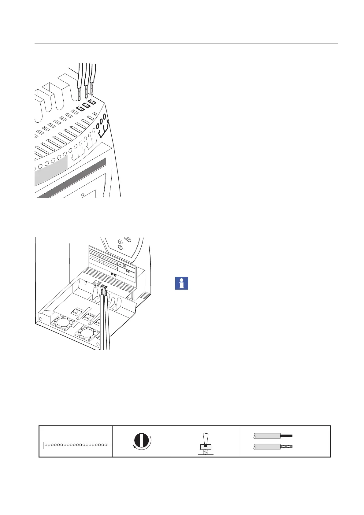
5:2.2.8 PTC input
If the motor is protected by PTC elements, the cables shall
be connected to terminals 23 and 24, see Figure 28.
See Chapter 7 “Settings and configuration” for programming.
The PTC input uses the same terminals as the Analog output
and only one of these functions can be used at any given time.
Figure 29:Tightening torques and cable dimensions (1 mm=0.0394 in)
In1
Vc
7
8
9
10
Vp
V
p
11
K4
12
13
14
Vn
15
16
K5
17
18
19
K6
20
1SFC132064F0001
igure 27: Terminals 18, 19, 20
LISTED 7F39
IND. CONT. EQ
.
1SFA 894 007 R
1002
IE
C
947-4-2
Ie
: 3
7
-7
2
A
U
s
: 1
0
0
-2
5
0
V
A
C
/D
C
U
L 508
U
c
: 1
0
0
-
2
5
0
V
A
C
/D
C
F
L
A
: 3
7
-6
8
A
Made in Sweden
U
e
:
2
2
0
-2
3
0
3
8
0
-4
0
0
5
0
0
V
72: A
C-53a: 8-1.6: 80-6
In
lin
e
1
8
,5
3
7
4
5
k
W
U
e
2
0
8
2
2
0
-2
4
0
4
4
0
-4
8
0
V
In
lin
e
2
0
2
0
5
0
H
p
CAUTION
F
u
s
e
2
5
0
A
T
Y
P
O
W
E
R
Z
IL
O
X
Ma
x
s
h
o
r
t c
irc
u
it
c
u
rre
n
t
6
5
k
A
a
t 4
8
0
V
W
ire
1
-8
A
l C
u
7
5
C
o
n
ly
, 3
5
lb
-in
O
v
e
rlo
a
d
C
a
p
a
c
ity
1
1
5
%
o
f
C
o
n
tin
u
o
u
s
Key-Pad
FELDBUSS
1SFC132065F0001
Analogue Output/PTC
23
24
igure 28: PTC connection
M3
1. . . . . . . . . . . . . . . . . . . . . . . . 20
0,5 Nm - 4,3 lb.in
3,5x0,6
0,14 ... 2,5 mm
AWG 12 ... 22
0,14 ... 2,5 mm
2
2
1SFC132053F0001
 Loading...