Human-Machine Interface (HMI)
Chapter 6
64
1SFC132003M0201
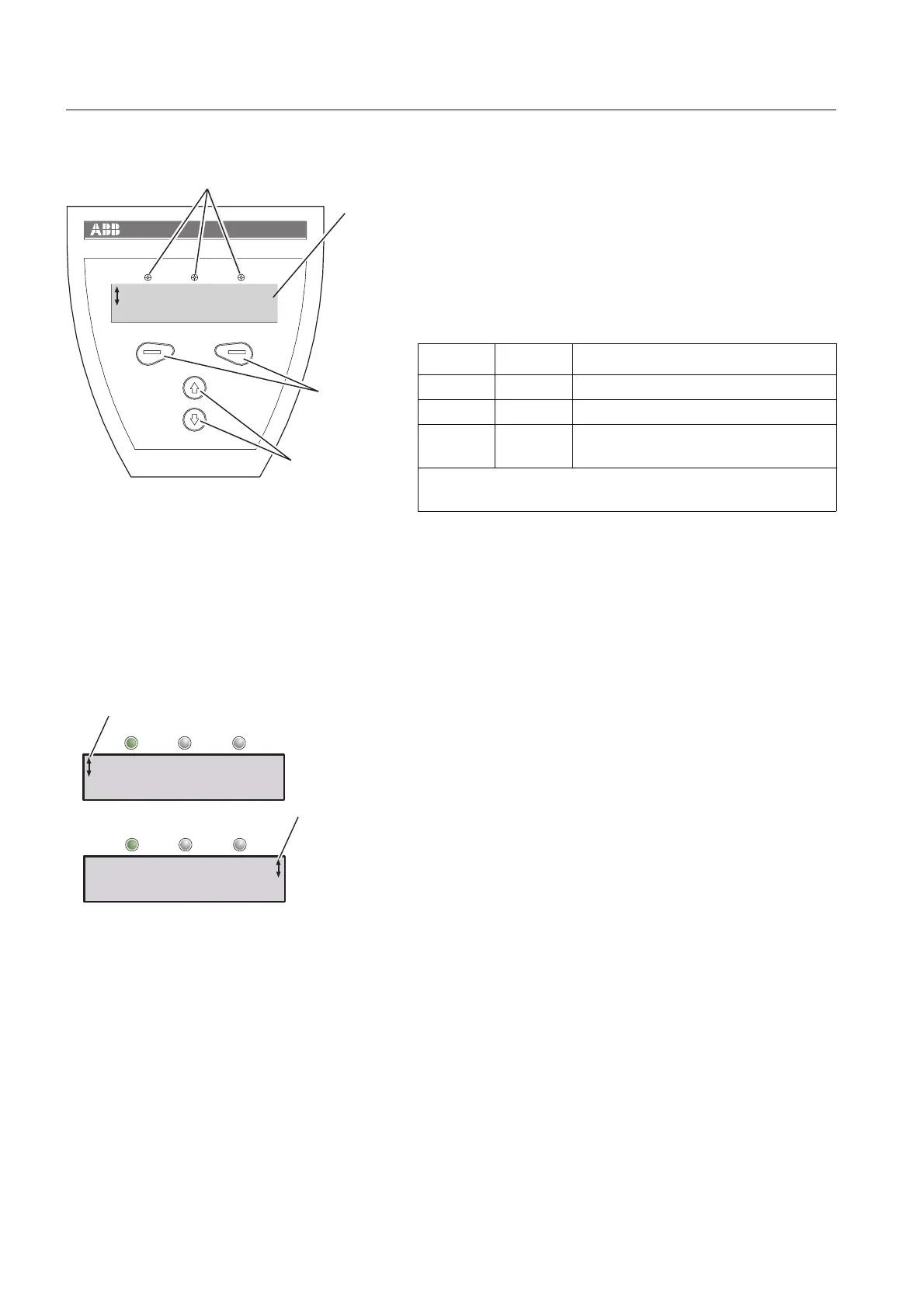
6:1.2 Design
The HMI consists of:
• Status indication LED indicators
• LCD display
• Selection and Navigation keys
The LED indicators work as follows:
The keypad is based on the same user concept as today’s
mobile phones.
The LCD display contains two rows which allow 20
characters each.
On the top row various information is presented, depending
on state. On the bottom row there are labels indicating which
function the selection keys currently have.
A scrolling icon indicates what parameter or setting value is
possible to change at the position.
The Selection keys normally have more than one function,
such as selecting, changing and storing, depending on
present dialogue, see text on the bottom row of the LCD
display.
The Navigation keys are used for navigating in the menus to
the desired setting.
When selecting from a list, the scrolling is done in a closed
loop.
LED Color Description
Power on Green Supply voltage connected.
Fault Red Indicates faults.
Protection Yellow Indicates that protections are acti-
vated.
When Fault or Protection LED is activated, the LCD display
displays the actual fault or protection.
Power on ProtectionFault
1
2
3
4
1SFC132029F0001
igure 1: Human-Machine Interface
1 Status indication LEDs
2 LCD display
3 Selection keys
4 Navigation keys
U= 0% I=0.0A
Menu
Power on ProtectionFault
Power on ProtectionFault
1
1
igure 2: Menu examples
1 Scrolling icons
Setting Ie 100A
Change Back
Setting Ie 100A
Store Cancel
 Loading...