Enova DGX DXLink™ Fiber Boards
116
Hardware Reference Manual – Enova DGX 100 Series Digital Media Switchers
System Setup with DXLink Fiber, Duplex and Simplex Units
DXLink Fiber Input and Output Boards must be used in conjunction with DXLink Fiber TX and RX units. Compatible DXLink Fiber
units are listed on page 112. System setup options are listed in the table on page 40. For unit installation details, see the units’
Quick Start Guide or Hardware Reference Manual.
When the TX and RX units are installed, image adjustment and EDID scaling is automatically applied. For almost every installation,
the automatic features on the units result in a quality image on the monitor. If the installation has special requirements and needs
additional adjustment or if you need product specifications for the modules, refer to the Hardware Reference Manual – DXLink Fiber
Transmitters and Receivers at www.amx.com.
The distance from a DXLink Fiber TX unit to a DXLink Fiber Input Board can be up to the maximum specified in the table below and
the same for the distance from the DXLink Fiber Output Board to the DXLink Fiber RX unit. The cable run length depends on the
quality of the cable (see specifications in the table below, which apply to both Duplex and Simplex hardware).
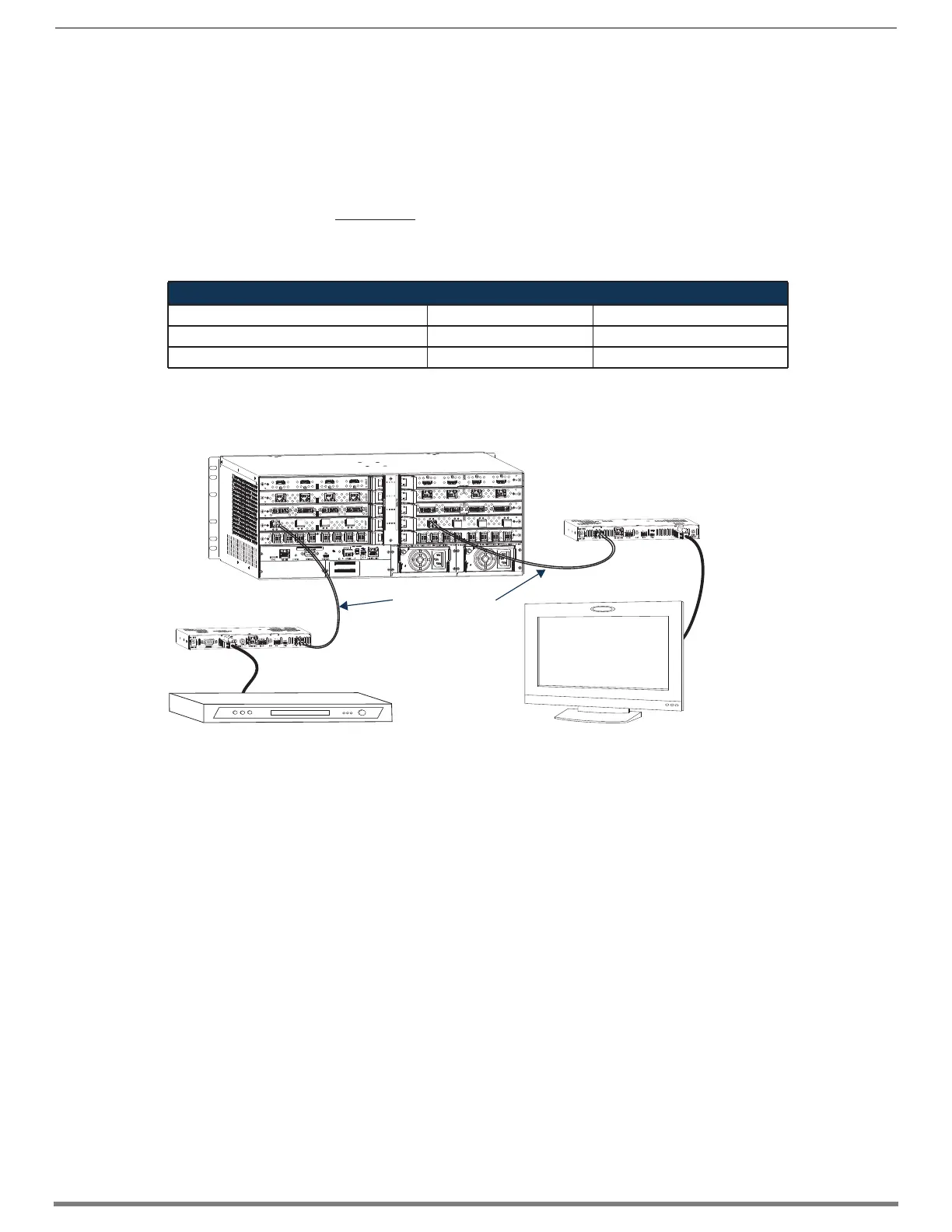
The system setup in FIG. 59 illustrates DXLink Fiber Boards, Duplex used in conjunction with a DXLink Fiber, Duplex Transmitter and
Receiver. Setup for DXLink Fiber, Simplex equipment is similar but without the return path.
IMPORTANT: Be sure to read “DXLink Fiber Hardware Compatibility” on page 111.
TIP: For systems with special requirements – Before installing in the final location, place the equipment close together, so the Control
PC and the destination monitor can be seen simultaneously if adjustments are necessary.
Destination Device Support Problems
Occasionally destination devices can cause problems in the system due to lack of signal support.
Audio – If you experience audio problems, it may be because you are trying to pass Dolby or DTS or high PCM frequency
rates and the destination device does not support them.
Video – If you experience video problems, it may be because you are trying to pass a video format that the destination
device does not support.
In either of these cases, configuring the EDID may help resolve the problem (see page 175).
DXLink Fiber Model / Cable / Distance
Model Cable Type Maximum Distance
Multimode – Duplex/Simplex Models OM3 50/125 μm 984 ft. (300 m)
Single mode – Duplex/Simplex Models 9/125 μm 6.21 miles (10 km)
FIG. 59 DXLink Fiber Boards are used in conjunction with DXLink Fiber units
AC
DC
FLT
AC
DC
FLT
NOTE: Fiber optic cable length
requirements differ between
multimode and single mode.
For cable length specifications,
see the table above.
Fiber Optic Cable
DXLink Fiber RX
DXLink Fiber TX
Enova DGX Switcher
Source Device
Destination
Device
 Loading...