Enova DGX Audio Insert/Extract Boards
160
Hardware Reference Manual – Enova DGX 100 Series Digital Media Switchers
4. Repeat Steps 1 through 3 as necessary for the remaining overlays.
Attaching Wires
When attaching audio wires, you may find it easier to unplug the audio connectors before you start.
For connector details, see Audio Specifications on page 155.
Important to Know When Wiring AIE Boards
Audio boards and connectors are positioned vertically on the Enova DGX 3200 and horizontally on the
Enova DGX 800/1600/6400. Be sure to note the labeling for the wiring on the “R” (right channel) and the “L” (left channel)
wires in FIG. 101.
Enova DGX 800/1600/6400 only – the orientation of Audio Insert/Extract Board in the right expansion slot places the
number 1 audio connector on the far right of the board.
CAUTION: Connecting AIE output left and Right channels to the same point to obtain a single channel may damage the AIE Board.
NOTE: If wiring the audio connectors to balanced audio input devices, see page 162 for options.
To wire audio connectors:
1. Press a very small tip screwdriver (or a T-pin) into the square hole to release the tension clamp (if the clamp does not release
fully, you may need to use the screwdriver as a lever to release it).
2. Insert the wire into the round hole.
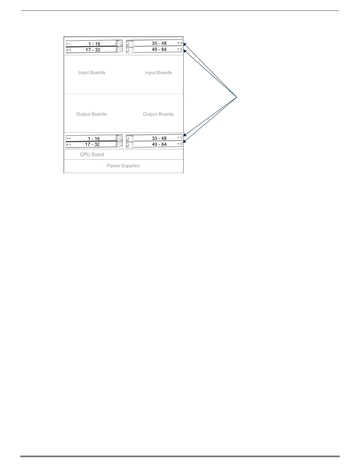
FIG. 100
AIE Board slot numbering on Enova DGX 6400
AIE slot numbering
in DGX 64
AIE Board Slots
 Loading...