Switching, Configuration, and Status
166
Hardware Reference Manual – Enova DGX 100 Series Digital Media Switchers
Switch Mode
The Switch Mode buttons allow you to choose between switching Audio follow Video (A/V), Video (with embedded audio), or Audio
only.
IMPORTANT: Support for the Audio Switch Mode (VM 2) requires Audio Switching Boards in the enclosure.
A/V and Video input and output ranges cover the basic switching size of the system: 8x8, 16x16, 32x32, or 64x64
Audio only input and output ranges cover the embedded audio as part of the basic switching size of the system, plus the
audio available on the Audio Switching Boards (ASB and ASB-DAN) in the expansion slots, plus the assignment of one input
as a downmixed audio channel:
Enova DGX 800: 1-8 embedded audio, 9-16 audio only, 17 downmix audio only
Enova DGX 1600: 1-16 embedded audio, 17-24 audio only, 25 downmix audio only
Enova DGX 3200: 1-32 embedded audio, 33-40 audio only, 41 downmix audio only
Enova DGX 6400: 1-64 embedded audio, 65-80 audio only, 81 downmix audio only
To execute a switch, click the Switch Mode button (otherwise the switch will default to A/V), an Input button, an Output button(s),
and the Take button. (This is called input-oriented switching, also known as one-to-many switching.)
NOTE: If you select an output button first (output-oriented switching, which can only be one-to-one switching), you must select an
input button next followed by the Take button, i.e., you cannot select additional outputs before you select the input. If you select an
output button first and then the input button, the only way to select multiple outputs is to click the Clear button and click the input
button followed by the output buttons.
To deselect (clear status) an input button that has already been selected, click another input button or click Clear.
To deselect (clear status) a single output button that has already been selected (before an input button), click another output
button or Click Clear.
To clear status of an input and any or all output buttons, click Clear.
To disconnect all currently selected outputs for an input, click the Deselect All button followed by clicking Take.
To execute a switch with a downmixed signal,* the Audio Switch Mode must be selected and the input used for the Downmix signal
must be selected on the Configuration page. Click the Downmix button, click the output(s), and click Take.
* Audio Switching Boards must be present for this functionality to work.
Configuring/Switching the Downmix Signal
When the system contains Audio Switching Boards (ASB or ASB-DAN), one embedded audio signal** can be downmixed and routed
at any given time.
** Signal must be Dolby Digital, Dolby TrueHD, DTS, DTS-HD Master Audio, or 2 CH through 8 CH L-PCM.
When Audio Switch Mode is selected, the “Downmix” input automatically displays as the last analog audio input+1. The Downmix
Input number for each of the Enova 100 Series models is shown in the following table.
NOTE: The table above also applies to Enova 8/16/32/64 enclosures that have been upgraded with an Enova DGX 100 Series CPU
and that contain Audio Switching Boards (ASB and ASB-DAN).
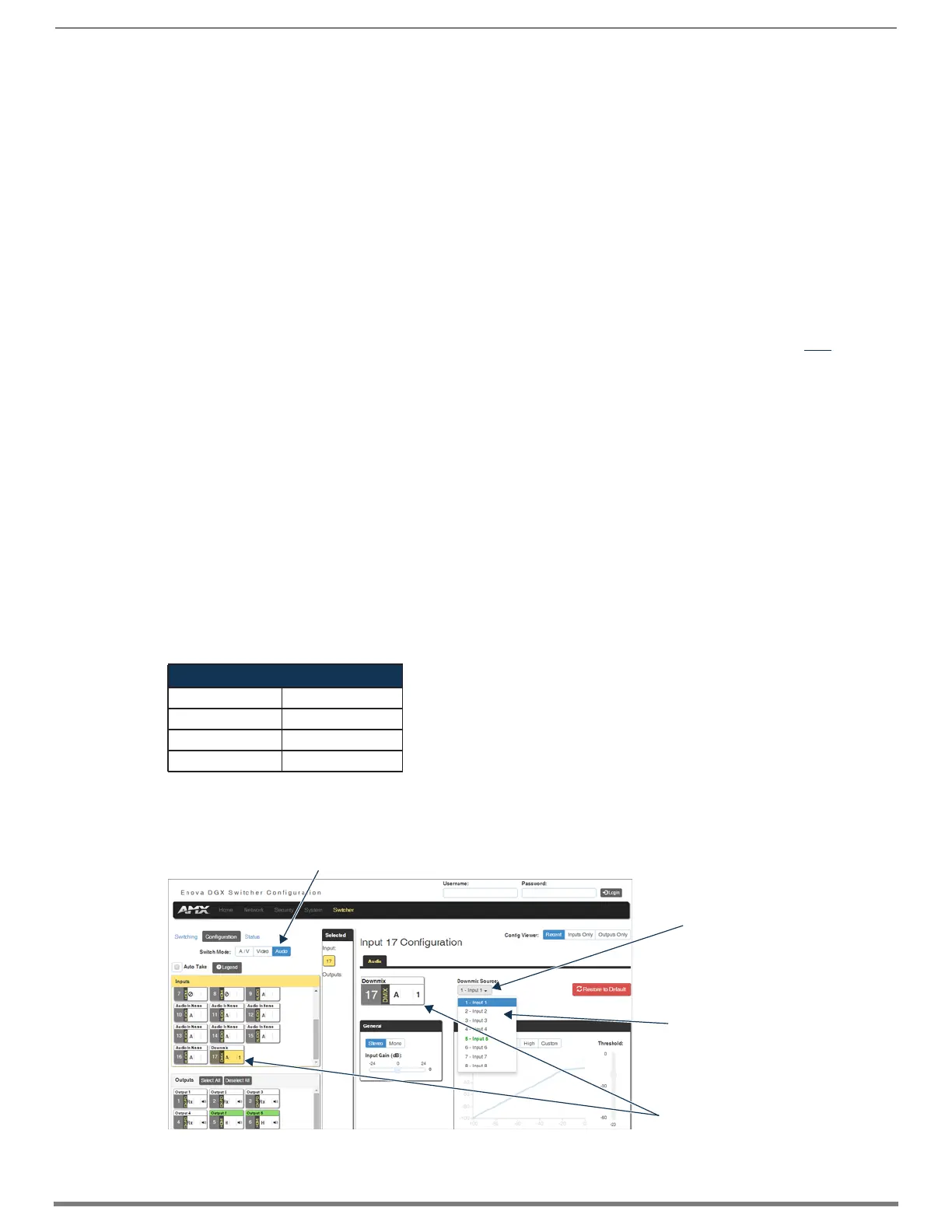
From the Configuration page – to designate the source to be routed on the Downmix Input, click the Downmix button in the
Switching pane on the left and select the input from the Downmix Source drop-down list in the Configuration pane on the right.
Downmix Input #
Enova DGX 800 17
Enova DGX 1600 25
Enova DGX 3200 41
Enova DGX 6400 81
FIG. 106 Downmix input ready to switch or configure
Switch Mode must be set to Audio
Drop-down list displays
inputs available for
downmixing
Downmix Source
routes the selected
input (Input 1 in the
example)
Downmix Input button
 Loading...