Enova DGX DXLink™ Twisted Pair Boards
93
Hardware Reference Manual – Enova DGX 100 Series Digital Media Switchers
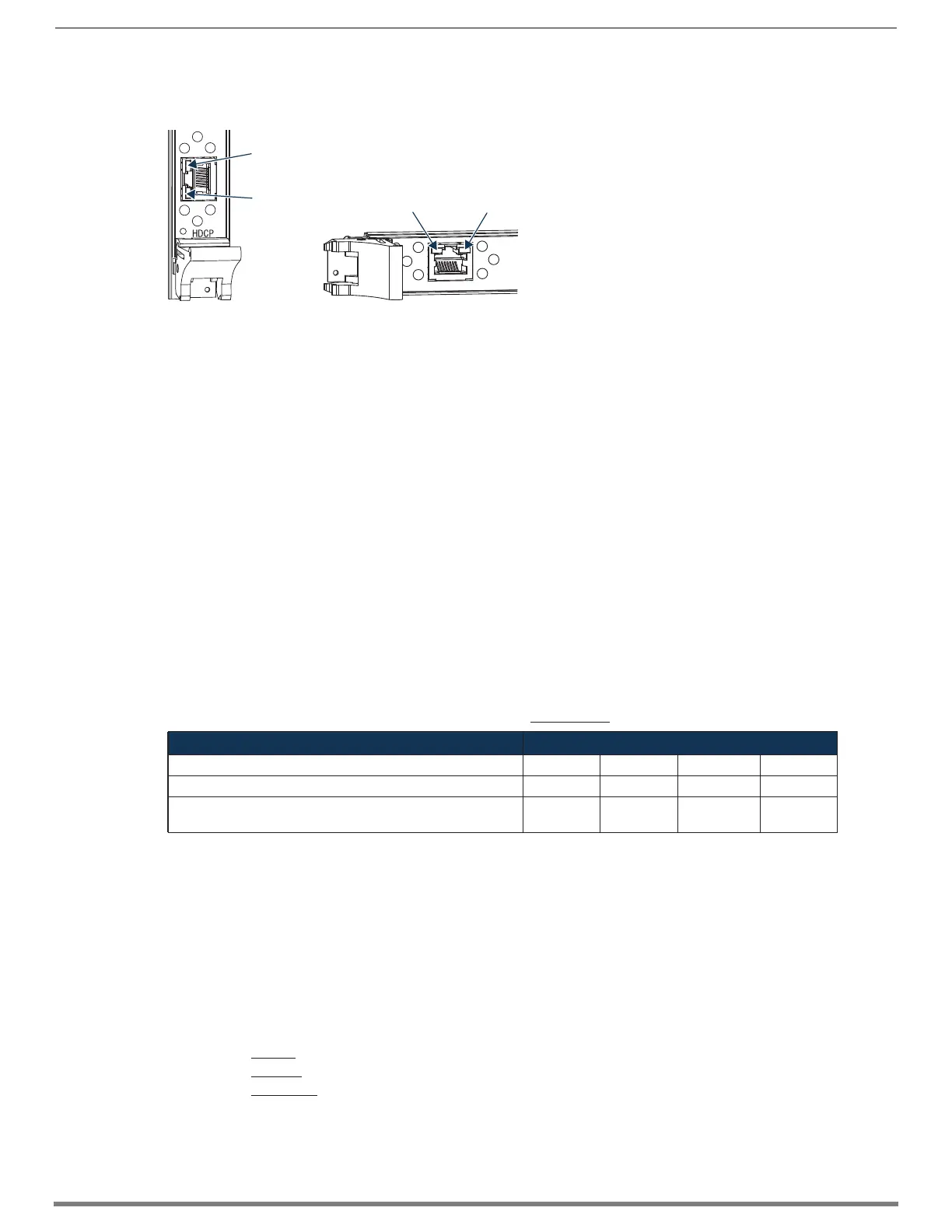
DXLink Connector LEDs
The following information applies to the LEDs on the DXLink connectors on the DXLink Input and Output Boards.
Configuring DXLink Endpoints for Communication with a Master
DXLink Transmitters and Receivers may be configured for communication in one of two ways: auto-setup or traditional NetLinx
binding. The instructions in this section cover configuration through auto-setup. For instructions that cover configuring TXs and
RXs through traditional NetLinx binding, see the Hardware Reference Manual – DXLink Twisted Pair Transmitters/Receiver.
DXLink endpoints ship from the factory with a default mode which allows auto-setup to work without additional configuration. If the
endpoint has not been altered from its default settings, it should not require any of the following instructions. For information of
control signals passed through an Enova DGX with configured DXLink Transmitter and Receiver, be sure to review “Serial Data
Transfer and IR Flow Control” on page 95.
Best Practices for Configuration
Best practices for configuring endpoints includes using auto-setup. Auto-setup is designed to reduce the number of IP addresses
consumed by a complete system. In a system that does not use auto-setup, each endpoint requires its own IP address whereas a
system that uses auto-setup requires only one IP address (for the integrated Master) and each endpoint is configured for
communication via a private LAN (ICS LAN) hosted by the integrated Master.
DIP Switch Toggles
The following table contains some of the most common scenarios for setting up DXLink Transmitters and Receivers with an Enova
DGX Switcher (the default for all four DIP switch toggles is OFF).
IMPORTANT: Find the scenario in the table below that you want to use and set the DIP switches accordingly.
The DIP switches are on the bottom of the DXLink Modules, on the rear of the DXLink Wallplate, and on the front of the DXLink Decor
Style Wallplate (hidden by front cover plate). A detailed description of functions for each toggle is provided in the Hardware
Reference Manual – DXLink Twisted Pair Transmitters/Receiver at www.amx.com.
* Connect the ICS LAN 10/100 port of the DXLink unit to the network device (e.g., laptop, IP controlled projector, AMX ICSLan EXB
device).
** #1 Toggle settings do not apply to Wallplate TX & Decor Wallplate TX – leave #1 Toggle OFF.
TIP: Each toggle’s ON position is toward the connectors on the rear of the DXLink Modules or toward the top of the unit for the DXLink
Wallplate TXs and Decor Wallplate TXs.
Auto-setup
To configure TXs and RXs using traditional NetLinx binding (requires disabling auto-setup), see the Hardware Reference Manual –
DXLink Twisted Pair Transmitters/Receiver.
Need to Know for Auto-setup
□ Endpoints must be set to DHCP Mode (default)
□ Endpoints must use NDP Master connection mode (default)
□ Endpoints must not be currently bound (traditional NetLinx binding) to a Master
□ Endpoint DIP switch setting for Toggle #3 (network connectivity) is ignored while in auto-setup mode
FIG. 49 DXLink connector LEDs (left Enova DGX 3200 Output Board orientation; right Enova DGX 800/1600/6400 orientation)
Common Scenarios DIP Switch Toggle Settings
Switcher Setup – TX/RX with Enova DGX 100 Series 1 2 3 4
AV with NetLinx control of TX/RX unit and serial/IR ports OFF OFF ON OFF
AV with NetLinx control of TX/RX unit and serial/IR ports, plus
Ethernet passthrough to networked device*
ON** OFF ON OFF
Yellow:
On – Authenticated HDCP
(handshaking has occurred
successfully)
Flashing – Video active; no HDCP
Off – No video
Green:
On – Speed status is 100 Mbps
Off – Speed status is 10 Mbps
Green LED
Yellow LED
Yellow LED
Green LED
 Loading...