Installation and Setup
41
Hardware Reference Manual – Enova DGX 100 Series Digital Media Switchers
Safety Recommendations for Laser Products
IMPORTANT: No user serviceable parts are included inside Enova DGX Switchers; service should only be done by qualified personnel.
CAUTION: Use of controls or adjustments or performance of procedures other than those specified herein may result in hazardous
radiation exposure.
Exercise caution when installing Enova DGX DXLink Fiber products to avoid direct eye exposure to invisible laser radiation. Follow
the recommendations below whenever installing or working with fiber products.
□ Be sure to apply the power only after all the fiber connections are made and no fiber ends are exposed.
□ Do not remove dust plugs from fiber connectors or the dust caps from the fiber cables until establishing connections; avoid
direct eye exposure.
□ Make sure all cables, including fiber cables, are correctly connected and/or terminated.
□ Before you unplug a fiber cable on an input board, disconnect the power on the transmitter that is connected to the input.
□ Before you unplug a fiber cable on an output board, disconnect the switch for that output connector.
Installation Procedure
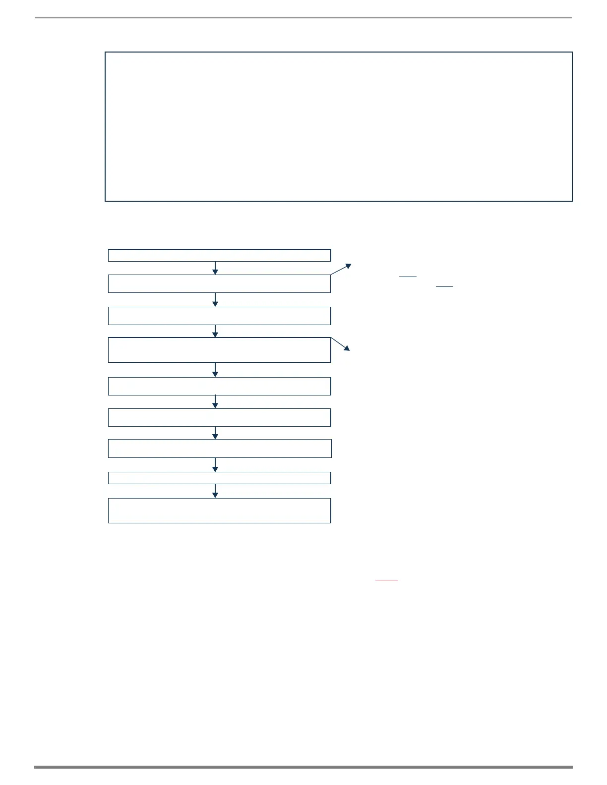
A flow chart showing the installation sequence is in FIG. 15. The procedure below the chart provides general steps with references
to detailed information found in later sections of the manual.
CAUTION: To prevent overheating and airflow restriction, avoid placing high heat producing equipment directly above or below the
enclosure. The system requires a minimum of one empty rack unit above and below (three empty rack units are recommended). Verify
that the openings on the top and sides of the enclosure are not blocked and do not have restricted air flow.
NOTE: If desired, remove any rubber feet present from bottom of enclosure before rack installation.
FIG. 15
Flow chart for installation procedure
Install in rack.
Attach first two video input and output cables.
If applicable, install appropriate TXs and RXs.
If applicable, wire first two connectors on audio board(s).
If applicable - attach cable management bars for
DXLink Fiber Boards.
Establish connection from integrated Master to public LAN via
LAN 100/1000 port on CPU.
Apply power to enclosure(s)
and then to system devices.
Launch System Configuration interface via browser
on PC connected to public LAN.
Execute a test switch.
Attach remaining video input and output cables.
If applicable, install remaining appropriate TXs and RXs.
If applicable, wire connectors on audio board(s).
IMPORTANT: If the system contains Audio Insert/Extract
Boards, they must be removed from the system and the DIP
switches on the boards must be set to either insert or extract
audio according to the system’s requirements (see page 157).
If applicable - remove AIE Audio Boards, set DIP switches
to insert or extract, and re-install in enclosure.
IMPORTANT: DXLink twisted pair cable runs for DXLink Input
and Output Boards shall only be run within a common
building. “Common building” is defined as: Where the walls of
the structure(s) are physically connected and the structure(s)
share a single ground reference.
 Loading...