Appendix G – External Serial Controllers
288
Hardware Reference Manual – Enova DGX 100 Series Digital Media Switchers
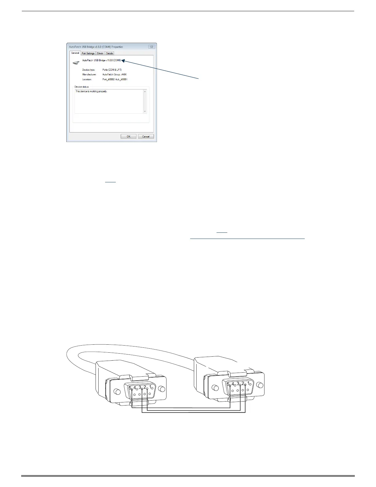
9. In the AutoPatch USB Bridge Properties dialog box, select the General tab.
10. Make note of the COM port number assigned to the AutoPatch USB Bridge. This port number must be entered when setting a
connection in a software program or a terminal emulation program. The PC will always associate a specific USB connector
with the assigned virtual COM port. The PC will not recognize the module if you disconnect and reconnect using a different
COM port on the PC. However, it will attempt to install a new virtual COM port using the new port. If completed, the new port
will be assigned a different COM number.
IMPORTANT: You must identify the virtual COM port assigned to the USB connector to enable communication between the Control PC
and the switcher.
11. Set up and run the desired method of control:
AMX Controller – For control programming information, see the manual for the specific controller.
Terminal Emulation – Open the program (see “Terminal Emulation” on page 289). Check to be sure the COM port is set for
the port determined in the previous steps. Set the settings to match the Enova DGX 100 Series defaults:
baud rate – 115200, data bits – 8, parity – 1, stop bits – none, and flow control – 1.
IMPORTANT: If power is cycled on the enclosure, the USB connection must be reestablished. (1) Remove the USB cable, (2) close the
software application in use, (3) reconnect the USB cable to the same USB connector that was used previously, and (4) reopen the
communication software.
External Serial Control via DB-9 Control Port
The DB-9 Control port provides a standard serial connection and can be used to connect directly to a control application or to a PC
running a terminal emulation program. To access the terminal emulation program in NetLinx Studio, go to Tools/Terminal Session.
PC Requirements for Serial Control
□ Windows 7 or Windows 8
□ Terminal emulation program
□ Serial port or USB port
RS-232 Pin Diagram
A serial connection via the Control port requires a null modem cable that matches the pin diagram in FIG. 153 for RS-232 without
hardware flow control. Enova DGX Switchers require pins 2, 3, and 5 only.
FIG. 153 RS-232 null modem cable pin diagram, no hardware flow control
Assigned port number
PC: DB-9
Enova DGX: DB-9
 Loading...