Installation and Setup
57
Hardware Reference Manual – Enova DGX 100 Series Digital Media Switchers
The following table lists the modes and the blink patterns for the Program port’s LED indicators which are associated with each
mode. These blink patterns are not evident until the unit is powered.
* “Normal” is typically off. However, this state may change depending on external inputs.
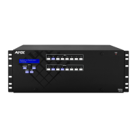
Attaching an AxLink Device
The CPU board has an AxLink port and an adjacent AxLink LED on its right. The AxLink port is a 4-pin mini-Phoenix (female)
captive-wire connector. This port allows the integrated Master to support AMX AxLink devices. The AxLink port can be used to
supply power to downstream AxLink-compatible devices as long as the power required does not exceed 2 Amps.
AxLink LED
A green AxLink LED indicates AxLink data activity. “Off” indicates either no power or the Master is not functioning properly.
When the AxLink port is operating normally, LED blink patterns include:
1 blink per second – Normal operation.
3 blinks per second – AxLink bus error. Check all AxLink bus connections.
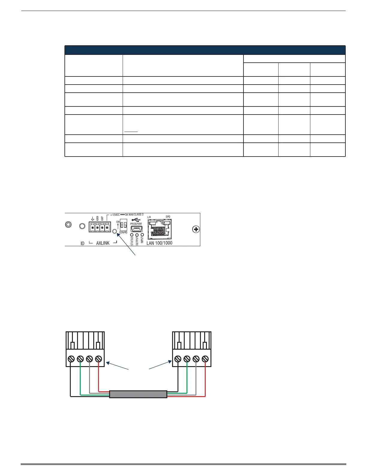
Using the AxLink Connector for Data and Power
To supply data and power to an AxLink compatible device, wire the AxLink connector as shown in FIG. 35.
Modes and LED Blink Patterns
Mode Description
LEDs and Blink Patterns
Status
(Green)
Output
(Red)
Input
(Yellow)
OS Start Starting the operating system (OS). On On On
Boot Integrated Master is booting. On Off On
Contacting DHCP Server Integrated Master is contacting a DHCP server for IP
configuration information.
On Off Fast Blink
Unknown DHCP Server Integrated Master could not find the DHCP server. Fast Blink Off Off
Downloading Boot
Firmware
Downloading Boot firmware to the integrated Master’s
flash memory.
Do not cycle power during this process.
Fast Blink Fast Blink Fast Blink
No program running Either no program is loaded or the program is disabled. On Normal* Normal*
Normal Integrated Master is functioning normally. 1 blink per
second
On indicates
activity
On indicates
activity
FIG. 34 AxLink Connector and LED
FIG. 35 AxLink connector wiring diagram (direct data and power)
Mo
es an
LED B
n
Patterns table
AXM = AxLink - (minus)
AXP = AxLink + (plus)
AxLink LED
GND
AXP/TX
AMX/RX
PWR
Top view
GND
AXP/TX
AMX/RX
PWR
AxLink port on compatible device
AxLink port on CPU
 Loading...