D9412GV4/D7412GV4 v2.03 | Installation and System Reference Guide | 21.0 Current Ratings Charts
.
Bosch Security Systems, Inc. | 7/16 | F01U265457-09 151
21.0 Current Ratings Charts
21.1 D8125MUX
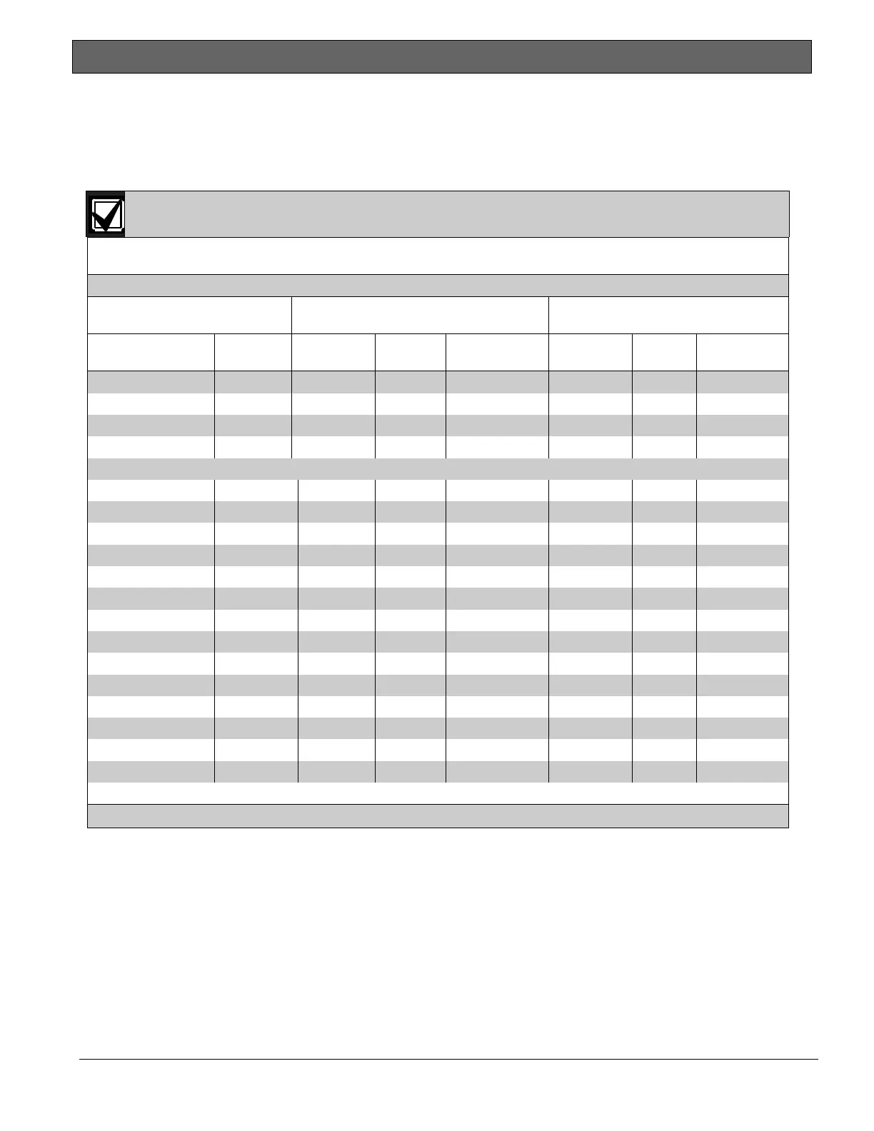
Complete the chart in Table 39 to determine the maximum currents for the D8125MUX and its
accessories. Transfer the total figures to Table 41 on page 152.
The maximum current draw for each MUX Bus is 75 mA.
Table 39: Current Rating Chart for D8125MUX
AC Power Off
Maximum Current (mA)
In Alarm
Maximum Current (mA)
Accessory
Module
Qty Used Each Unit Qty Total System Each Unit Qty
Total
System
DS7432 ________ 10 x Qty = _________ 10 x Qty = _________
DS7457i ________ 0.35 x Qty = _________ 0.35 x Qty = _________
DS7460i ________ 1 x Qty = _________ 1 x Qty = _________
DS7465i ________ 1 x Qty = _________ 1 x Qty = _________
Ratings of other devices on the MUX Buses that are not shown above*:
_______________ _________ ________ x Qty = _________ _________ x Qty = _________
_______________ _________ ________ x Qty = _________ _________ x Qty = _________
_______________ _________ ________ x Qty = _________ _________ x Qty = _________
_______________ _________ ________ x Qty = _________ _________ x Qty = _________
_______________ _________ ________ x Qty = _________ _________ x Qty = _________
_______________ _________ ________ x Qty = _________ _________ x Qty = _________
_______________ _________ ________ x Qty = _________ _________ x Qty = _________
_______________ _________ ________ x Qty = _________ _________ x Qty = _________
_______________ _________ ________ x Qty = _________ _________ x Qty = _________
_______________ _________ ________ x Qty = _________ _________ x Qty = _________
_______________ _________ ________ x Qty = _________ _________ x Qty = _________
_______________ _________ ________ x Qty = _________ _________ x Qty = _________
_______________ _________ ________ x Qty = _________ _________ x Qty = _________
_______________ _________ ________ x Qty = _________ _________ x Qty = _________
Column A Total = _________ Column B Total = _________
* Refer to the device’s installation guide for current draw values.
21.2 Standby Battery Calculations
UL 365 requires 72 h of standby battery capacity. Limit the auxiliary power current for all devices,
including keypads, to 300 mA or less to meet this requirement.

 Loading...


