D9412GV4/D7412GV4 v2.03 | Installation and System Reference Guide |
.
Bosch Security Systems, Inc. | 7/16 | F01U265457-09 68
11.4 Keyswitch
11.4.1 Description
A maintained or momentary contact arming
station (keyswitch) can be connected to turn
all on (arm) or off (disarm) any of the areas in
the system. The keyswitch is connected to an
input point (on-board, D9127U/T, D8128D, or
B208). Outputs can be programmed to activate
arming status LEDs for keyswitch arming
stations. Refer to Outputs in the Control Panels
(Control Panels (D9412GV4/D7412GV4 v2.03))
Program Entry Guide (P/N: F01U265459).
11.4.2 Programming
Refer to Point Assignments in the Control Panels
(D9412GV4/D7412GV4 v2.03) Program Entry
Guide (P/N: F01U265459) for the correct
programming for points used for keyswitches.
11.4.3 Installation
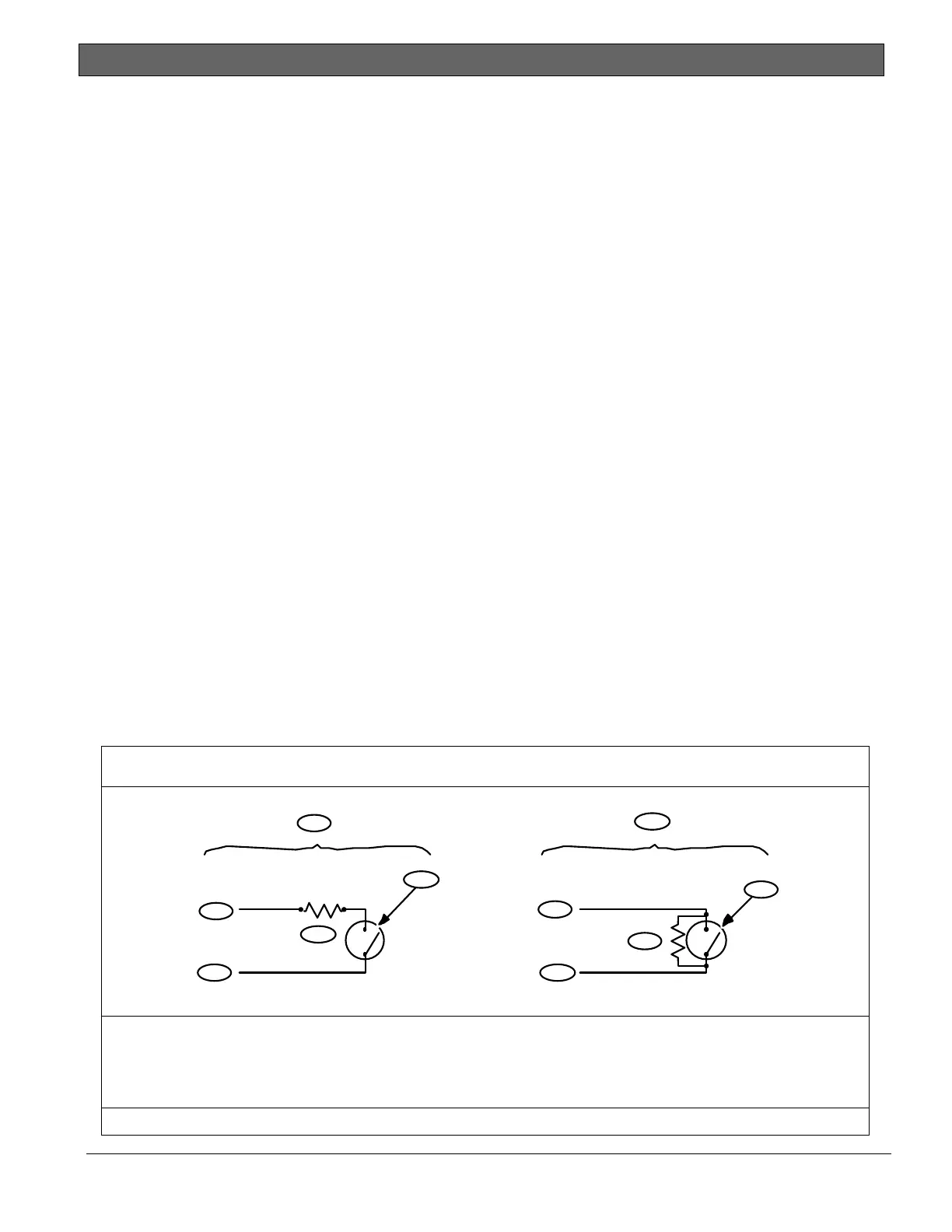
For maintained switches, connect the EOL
resistor for the point at the keyswitch so that
the switch opens the circuit when it operates.
A short on the circuit produces an alarm if the
area is turned on (armed) and a trouble if it is
turned off (disarmed). Refer to Figure 27 on
page 68 for momentary keyswitches, connect
the EOL resistor at the keyswitch point so that
when the keyswitch operates, it shorts the
resistor. An open on the circuit causes an
alarm if the area is turned on and a trouble if it
is turned off.
11.4.4 Operation
Maintained Contact
If the point to which the keyswitch is
connected is programmed for a maintained
contact, an open on the arming circuit arms
the area. All faulted points are force armed,
regardless of the entry in the FA Bypass Max
program item. Returning the circuit to normal
disarms the area. Refer to Area Parameters and
Point Assignments in the Control Panels
(D9412GV4/D7412GV4 v2.03) Program Entry
Guide (P/N: F01U265459).
Momentary Contact
If the point to which the keyswitch is
connected is programmed for a momentary
contact, shorting the arming circuit toggles the
area’s arming state between armed and
disarmed. All faulted points are force armed,
regardless of the entry in the FA Bypass Max
program item. Refer to Point Assignments in the
Control Panels (D9412GV4/D7412GV4 v2.03)
Program Entry Guide (P/N: F01U265459).
Silencing the Bell
To silence the bell (stop Alarm Bell output) if
the system is armed, position the keyswitch to
disarm the area. If the area is disarmed, turn
the keyswitch once to start the arming
process. Turning the keyswitch a second time
stops the arming process and silences the bell.
Figure 27: Keyswitch Wiring
1 - Maintained keyswitch
2 - Momentary keyswitch
3 - Common
4 - Point input
5 - End of Line (EOL) resistor
6- Open on a circuit arms the area
7 - Short on a circuit toggles the arming state
Use the proper EOL for the specific device you are using.
1
2
3
4
5
3
4
5
6
7

 Loading...


