D9412GV4/D7412GV4 v2.03 | Installation and System Reference Guide | Appendix A: System Wiring Diagrams
.
Bosch Security Systems, Inc. | 7/16 | F01U265457-09 165
A.4 SDI2 Bus Wiring Recommendations
Use the following SDI2 Bus wiring recommendations for SDI2 installation. The SDI2 Bus is used by the
GV4 Control Panel and corresponding modules to communicate with one another. Modules can be
connected via home run, daisy chain, or single level T-Tap anywhere on the SDI2 bus. Please reference
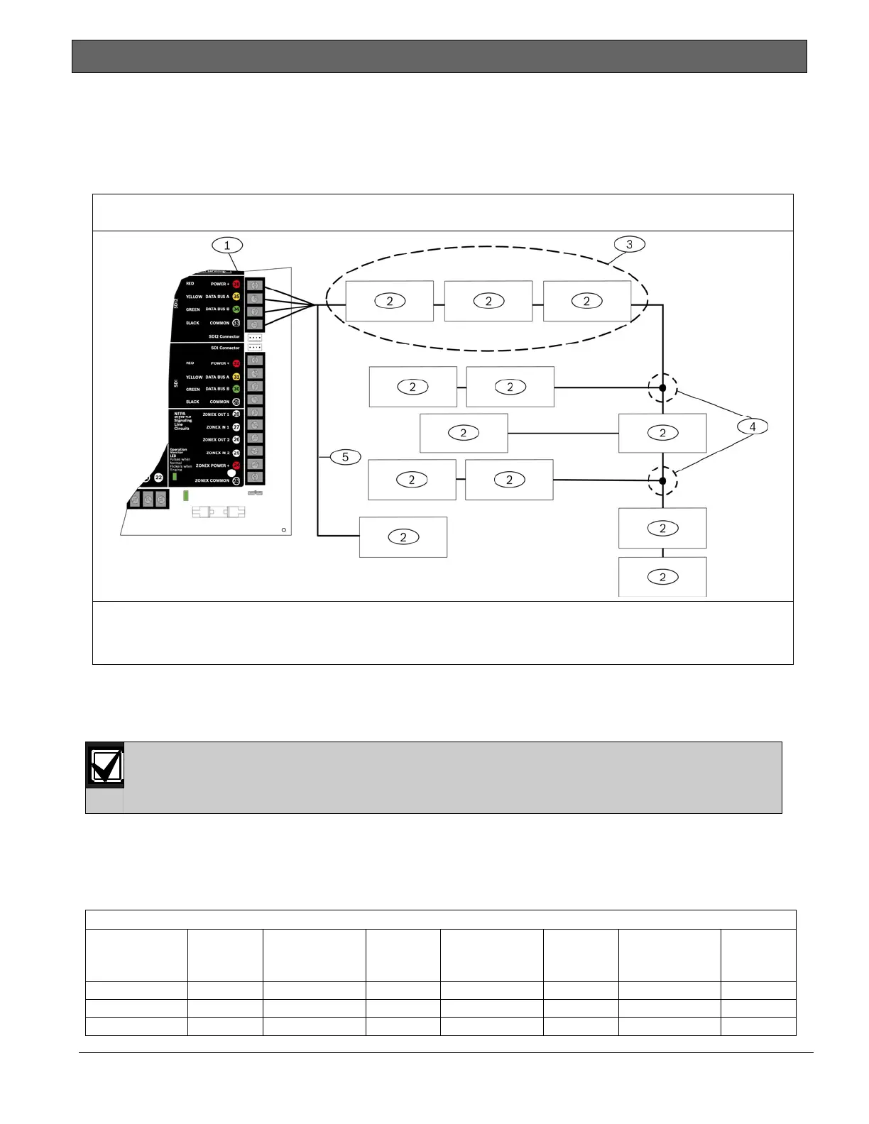
Figure 45 below.
Figure 46: SDI2 Bus Wiring
1 - Control panel
2 - SDI2 module
3 - Daisy chained wiring
4 - Single-level T-tapped wiring
5- Home run wiring
If the voltage at any device is below the minimum, you must add an auxiliary power supply to the
system to power these devices.
The absolute lowest voltage for the SDI2 devices is 10 VDC at the devices terminals when in
normal operation, with a fully charged battery on the system.
Maximum cable lengths
The following rules must be followed when wiring the SDI2 bus.
The SDI2 bus requires the use of non-shielded cable from 12 AWG to 22 AWG.
Maximum overall cable length based on the table listed below:
Table 48: Maximum Cable Lengths
Cable
Capacitance
Overall
Cable
Length
Cable
Capacitance
Overall
Cable
Length
Cable
Capacitance
Overall
Cable
Length
Cable
Capacitance
Overall
Cable
Length
Pf/ft ft Pf/ft ft Pf/ft ft Pf/ft ft
< 17 7500 22 6363 27 5185 32 4400
18 7500 23 6086 28 5000 33 4242

 Loading...


