D9412GV4/D7412GV4 v2.03 | Installation and System Reference Guide | 13.0 SDI2 Devices
.
Bosch Security Systems, Inc. | 7/16 | F01U265457-09 75
Table 27: Address switch settings
Control
panels
Switch
position
Control
panel
bus
addres
s
Bus
type
Function
USB or
SMS
config
setting
0 N/A Any
Change
config
B5512
B4512
B3512
D9412GV4
D7412GV4
1 1 SDI2 Automation,
RPS, or
Reporting
D9412GV4
D7412GV4
D7212GV4
2 2 SDI2 Automation,
RPS, or
Reporting
D9412GV4
D7412GV4
D7212GV4
D9412GV3
D7412GV3
D7212GV3
4 88 SDI
1
RPS or
Reporting
D9412GV4
D7412GV4
D7212GV4
D9412GV3
D7412GV3
D7212GV3
5 92 SDI
1
RPS or
Reporting
1
For D9412GV4/D7412GV4/D7212GV4 configurations,
SDI2 bus connection is the recommended configuration
option, but SDI bus configuration is also supported.
13.6 B426 Ethernet Communication
Module
B426 Ethernet Communication Module is a
four-wire powered SDI2 device that provides
connection for two-way communication over
Ethernet networks to the control panel. The
B426 uses the standard IPv4 or IPv6 address
protocol. You can add up to two B426 Ethernet
Communication Modules.
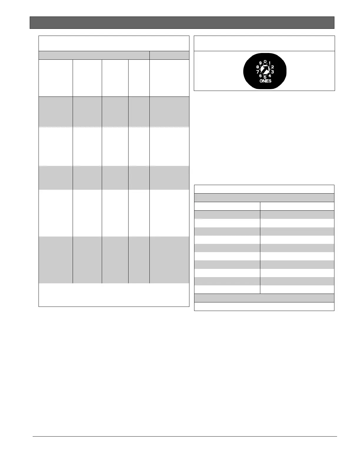
13.6.1 Address and Emulation Settings
The B426 address switche provides a single-
digit setting for the module’s address. The
module uses addresses 0 through 9. Refer to
Figure 32.
Figure 32: B426 Switch Set to Address 1
The B426 has specific rotary switch settings
for SDI Addresses 88 and 92 or SDI2
Addresses 1 and 2 when used to communicate
with Remote Programming Software (RPS) or
with a central station network receiver. Refer
to Table 28 for the correct switch settings.
When the Reset Pin (labeled S1) is closed, all
SDI communication module addresses are
automatically enabled for RPS communication
without restriction.
Table 28: B426 Address and Emulation Settings
Rotary Switch Setting Bus Type and Setting
0 Default
1 SDI2 ‒ Address 1
2 SDI2 ‒ Address 2
3* SDI ‒ Address 80
4* SDI ‒ Address 88
5* SDI ‒ Address 92
6* N/A for GV4
7* N/A for GV4
8* N/A for GV4
9* N/A for GV4
*
Emulates DX4020 operation.
13.6.2 Supervision
Supervision of Ethernet Communication
Modules at SDI2 Addresses 1 and 2 are
enabled automatically when used to
communicate with a central station network
receiver. Supervision ensures reliable
operation between the module and the control
panel.
If supervised and the module does not respond
to control panel supervision polls, then a
system fault message appears at the keypads.
A corresponding report is sent to the central
station.

 Loading...


