D9412GV4/D7412GV4 v2.03 | Installation and System Reference Guide | 4.0 Installation
.
Bosch Security Systems, Inc. | 7/16 | F01U265457-09 20
4.0 Installation
4.1 Installation Preparation
This section contains a general installation
procedure and refers to other sections of the
document for detailed instructions.
Review this document and the Control Panels
(D9412GV4/D7412GV4 v2.03) Program Entry
Guide (P/N: F01U265459) before beginning the
installation to determine the hardware and wiring
requirements for the features used.
Have the following documentation available when
reading through this guide:
Control Panels (D9412GV4/D7412GV4
v2.03) Control Panel Owner’s Manual.
Before installation, become familiar with the
operation of RPS or the local Programmers menu.
4.2 Enclosure Options
Mount the control panel assembly in any of the
Bosch Security Systems, Inc. enclosures listed:
D8103 Universal Enclosure (tan)
D8109 Fire Enclosure (red)
D8108A Attack Resistant Enclosure (tan)
Refer to chapter 17.0 Approved Applications in
this guide to determine if the application requires
a specific enclosure.
4.3 Mounting Enclosure
1. Run the necessary wiring throughout the
premises.
2. Mount the enclosure in the desired location.
Use all five enclosure mounting holes. Refer
to Figure 2.
3. Pull the wires into the enclosure.
Electromagnetic interference (EMI)
can cause problems on long wire runs.
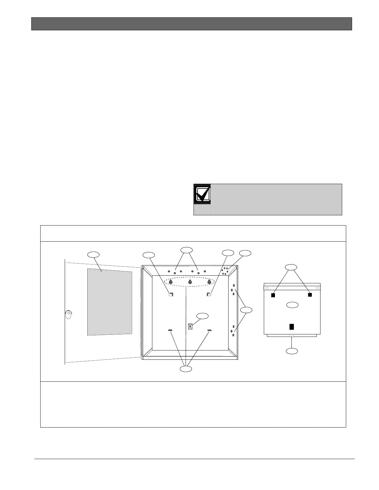
Figure 2: Enclosure Mounting
1 - Point chart label
2 - Mounting skirt hooks (2)
3 - Module mounting holes (12)
4 - Tamper switch mounting holes (5)
5 - Skirt mounting hole (1)
6 - Enclosure mounting holes (5)
7 - Mounting skirt hook holes (2)
8 - Back of D9412GV4/D7412GV4 Control Panel
9 - Lock down tab
8
2
1
3
2
4
3
7
5
9
6

 Loading...


